
Aircraft thermal energy harvesting using rotary shape memory alloy apparatus

a technology of memory alloy and aircraft, which is applied in the direction of mechanical equipment, machines/engines, gas turbine plants, etc., can solve the problems of large number of electrical systems on modern aircraft, requiring a significant amount of heavy and complex wiring, and generating only small amounts of electrical power

Active Publication Date: 2018-08-21
THE BOEING CO
View PDF26 Cites 0 Cited by
  • Summary
  • Abstract
  • Description
  • Claims
  • Application Information

AI Technical Summary

Benefits of technology

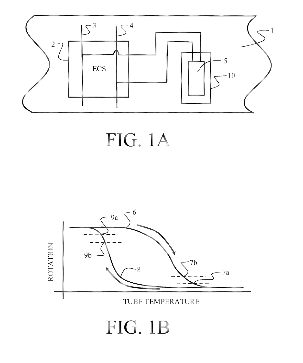
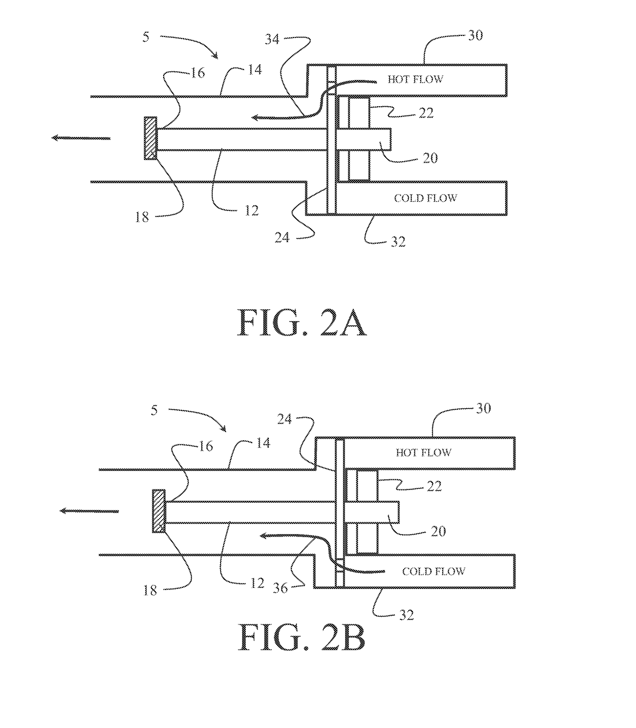
The patent describes a system for harvesting thermal energy using a hot flow conduit and a cold flow conduit with a flow routing device. A shape memory actuator (SMA) tube is in fluid contact with the flow casing and fixed at one end. The flow routing device sequentially supplies hot flow and cold flow to induce rotation of the SMA tube. A generator or alternator is operably connected to the other end of the SMA tube. The patent also describes a method for training the SMA tube with a twist direction and driving a generator / alternator through a gear box. The technical effect of the patent is to provide a system and method for efficiently harvesting thermal energy using a SMA tube.

Problems solved by technology

Additionally the large number of electrical systems on modern aircraft also requires a significant amount of heavy and complex wiring.
These methods often produce large motions, but very little work and only small amounts of electrical power are generated.

Method used


Image

  • Aircraft thermal energy harvesting using rotary shape memory alloy apparatus
  • Aircraft thermal energy harvesting using rotary shape memory alloy apparatus
  • Aircraft thermal energy harvesting using rotary shape memory alloy apparatus

Examples


first embodiment

[0034]An exemplary physical implementation of the thermal energy harvesting system 10 employing first embodiment of the SMA rotary motion generator is shown in FIGS. 5A and 5B. The flow casing 14, seen in FIG. 5A, houses the tube 12, seen in FIG. 5B. The end cap 18 constrains the tube 12 at the first end 16 and is attached to the flow casing 14. Exhaust apertures 46 in the end cap 18 allow the flow of gas to exit the flow casing 14. The rotating end of the tube 12 extends through the bearing 22 and is attached through a gear box 48 to a generator or alternator 50 to produce electrical power. The gear box 48 may include ratchets or other rotational direction conversion systems to provide single directional rotation from the gear box to the generator / alternator.

[0035]The rotational sequence of the baffle plate 24 described with respect to FIGS. 3A and 3B is shown in detail for the physical implementation in FIGS. 6A-6D. As seen in FIG. 6A, with the tube 12 in an initial position, the ...

second embodiment

[0036]A continuous output rotation in a single direction for driving a generator / alternator is achieved in a second embodiment as shown in FIGS. 7A and 7B. A plurality of SMA tubes, four tubes 12a, 12b, 12c and 12d for the exemplary embodiment shown in the drawings, are supported in a frame 52. Rotation of each tube drives a gear 54a, 54b, 54c and 54d which, in turn drives a central drive gear 56. The first end 16a, 16b, 16c and 16d of each tube is fixed to a ratchet gear 58a, 58b, 58c and 58d constrained against reverse rotation by a ratchet pawl 60a, 60b. 60c and 60d. The hot flow conduit 30 and cold flow conduit 32 are routed through a manifold 61 which incorporates a solenoid valve 64a. 64b, 64c and 64d for each tube controlling flow into a respective inlet conduit 65a, 65b, 65c and 65d. A central bore 13 (shown in phantom for example in tube 12a) in each SMA tube provides a flow casing connected to the respective inlet conduit to provide gas flow to heat and cool each SMA tube ...


PUM


Abstract

A thermal energy harvesting system employs a hot flow conduit and a cold flow conduit with a flow routing device interruptibly interconnecting the hot flow conduit and cold flow conduit with a flow casing. At least one shape memory actuator (SMA) tube is in fluid contact with the flow casing and fixed at a first end. The flow routing device sequentially supplies hot flow from the hot flow conduit and cold flow from the cold flow conduit inducing rotation of the at least one SMA tube at a second end. A generator or alternator is operably connected to the second end of the at least one SMA tube.

Description

REFERENCES TO RELATED APPLICATIONS[0001]This application is a continuation-in-part of application Ser. No. 14 / 566,376 filed on Dec. 10, 2014 entitled SCALABLE MULTI-ELEMENT SHAPE MEMORY ALLOY ROTARY MOTOR now issued as U.S. Pat. No. 9,885,345 having a common assignee with the present application, the disclosure of which is incorporated herein by reference.BACKGROUND INFORMATION[0002]Field[0003]Embodiments of the disclosure relate generally to thermal energy harvesting for electrical power and more particularly to a system employing alternating flow control of hot and cold air streams through a shape memory alloy (SMA) tube providing rotation to an output shaft connected to a generator.[0004]Background[0005]There is a growing need for electrical power on modern aircraft. Everything from flight control surfaces to entertainment systems require more and more electrical power. At the same time, in the face of increasing demands for reduced emissions, engines are becoming more and more e...

Claims


Application Information

Patent Timeline
Patent Type & Authority Patents(United States)
IPC IPC(8): F02C6/04F03G7/06
CPCF03G7/065F02C6/04
Inventor MABE, JAMES H.HUSSAIN, NAVEED M.WHALEN, EDWARD A.CALKINS, FREDERICK T.
Owner THE BOEING CO
Learn More