Thermoformed flexible dispensing container with integrally formed flat bottom for a stand-up configuration

a flexible and stand-up configuration technology, applied in the direction of packaging, transportation and packaging, successive articles, etc., can solve the problems of increasing the amount of waste packaging material that must be subjected to proper disposal, the complexity of multiple methods of fabricating the gusset, and the relative higher cost associated with their production. , to achieve the effect of lowering the center of gravity

Active Publication Date: 2018-08-28
BARTON GRP LLC
View PDF60 Cites 4 Cited by
  • Summary
  • Abstract
  • Description
  • Claims
  • Application Information

AI Technical Summary

Benefits of technology

[0011]The above problems are resolved and numerous other advantages and benefits are realized by the improved thermoformed flexible container of the present invention that has an integral flat, or planar supporting base configured and dimensioned for a stable stand-up package orientation during use in which the container portion is formed with a supporting flat base and the integral opposing side walls and the rear wall extending from the flat base terminate either at a top wall opposite the flat base or in a peripheral region that is heat-sealed to a top cover sheet so that the filled and sealed flexible container expands above the base to lower the center of gravity of the flexible package, allowing the user to stand the package on its flat base prior to and during use as the contents are withdrawn or dispensed.
[0013]When filled, e.g., with a liquid “L” and the base of the container portion is placed on a horizontal surface, the product, whether it be a beverage, a more viscous liquid or a flowable solid will gravitate or settle and expand the flexible side walls extending from the base. The package is thereby reconfigured from the planar shape as originally defined by, and formed in the package the die, and results in having a lower, stabilizing center of gravity. Flexible packaging so configured and dimensioned will produce a stand-up feature allowing the user to dispense or withdraw a portion of the liquid, return the package to the surface, and then, at a later time, withdraw the balance of the product from the package.
[0015]In the mass production of the flexible dispensing packages of this invention, the molds or dies are advantageously configured and arranged on the HTFFS machine in the manner illustrated and described in FIG. 6F of US 2015 / 0090740. The configuration illustrated facilitates the die-cutting to separate the individual packages and also reduces the waste material from the continuous web fed to the machine. As discussed above, the dies or molds shown in FIG. 6F and elsewhere in US 2015 / 0090740 can be modified to produce the embodiment of the present invention without the internal extension of the dispensing tube by eliminating the internal wall 620 shown in the series of FIGS. 6A, 6B and 6F.
[0017]In another embodiment of the invention, the horizontal die of the HTFFS machine is configured with a container portion in which the bottom wall that is opposite the opening in the die forms the base with opposing side walls extending between front and rear walls and the front wall extends to a greater depth in the die. In this embodiment, the front side wall is preferably provided with a dispensing tube having an internal extension. After the cover or lidding is heat-sealed to the periphery of the container portion and, optionally, to complete the closing of the dispensing tube, the periphery is sealed. When the filled package is removed from the die, the contents will cause the side walls to expand and leave an air space between the surface of the liquid and the cover sheet when the package is placed on a horizontal surface. It will be understood that a package of this configuration will require a base having a relatively larger area and provides a lower profile than the previously described embodiment. The orientation of the dispensing straw, if provided, will be at an acute angle to the horizontal as opposed to the essentially vertical orientation of the previously-described embodiment. This particular configuration forming a “flat” package permits easy stacking for storage and / or transportation, and may find an advantageous use with individuals having special needs, e.g., a bedridden patient who may find it easier to reach the dispensing tube extending at a relatively low angle from a bedside tray or table.
[0023]It will also be understood by those of ordinary skill in the art that flexible dispensing packages used for products sold at retail establishments can be formed from polymeric web materials of the same or different thickness and that the choice can be based on economic considerations. That is, use of one sheet or web that is of a thinner gauge than the thermoformed sheet will incur less cost per square unit of measure. Flexible packages used for lubricants, medicinal substances or in industrial applications can also require heavier gauge materials, which also can be of the same or different thicknesses.

Problems solved by technology

These types of prior art packages have several drawbacks including the complexity of multiple methods of fabricating the gusset, the additional material required and the relatively higher cost associated with their production.
The use of this heavier gauge material results in an added amount of waste packaging material that must be subjected to proper disposal.
In the present era of both governmental and consumer concern with the adverse impact of waste packaging materials on the environment and the costs associated with their recovery and proper disposal, the problem exists of providing a truly lightweight, but robust and durable form of packaging to replace glass, plastic and paperboard containers.
However, gusseted packages cannot be produced on the conventional HTFFS machines without significant modifications to accomplish additional folding steps and possibly an additional web.

Method used


Image

  • Thermoformed flexible dispensing container with integrally formed flat bottom for a stand-up configuration
  • Thermoformed flexible dispensing container with integrally formed flat bottom for a stand-up configuration
  • Thermoformed flexible dispensing container with integrally formed flat bottom for a stand-up configuration

Examples


Embodiment Construction

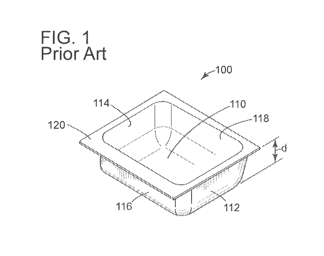
[0037]Referring to FIGS. 1 and 2, simplified representations of two dies of the prior art for producing corresponding thermoformed flexible containers of regular generally rectilinear configurations are shown. In FIG. 1, the die 100 includes container portion 110 having opposing side walls 112, 114, and front and rear walls 116, 118, respectively. The walls are of a uniformed height “d”, and are bounded by a peripheral area 120.

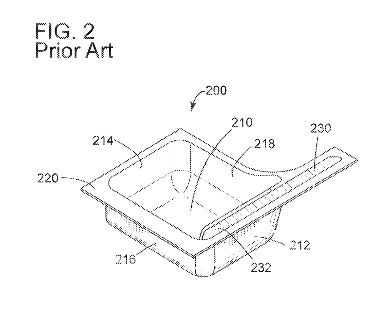
[0038]In FIG. 2, the prior art die 200 includes similar elements numbered correspondingly, but the die includes a dispensing tube 230 having an internal extension 232 to provide the user with access to liquid contents at the base of the container when the tube is oriented in a vertical position.

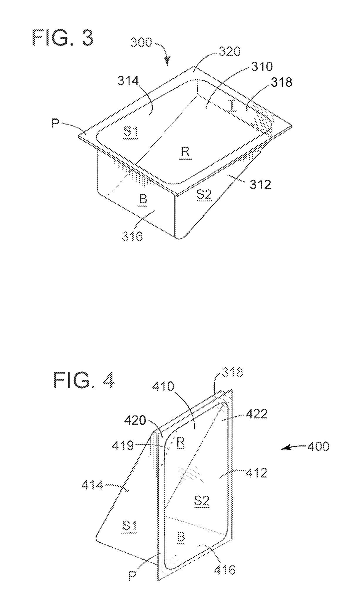
[0039]FIGS. 3 through 9 illustrate, respectively, dies and the corresponding packages having supporting flat bases in accordance with the invention produced in the dies, including representative packages with dispensing tubes that serve as drinking straws in FIGS. 7 th...


PUM

PropertyMeasurementUnit
flexibleaaaaaaaaaa
gravityaaaaaaaaaa
areaaaaaaaaaaa

Abstract

A flexible thermoformed dispensing package for a flowable material that can be massed produced on a horizontal thermoform-fill-seal (HTFFS) machine includes a container portion that is dimensioned and configured with a flat self-supporting base, integral opposing side walls and a rear wall extending from the base, and a top wall or seam integrally formed from a single sheet or web, the side walls tapering from the base toward the integral rear wall and terminating at the top wall or seam; and a front wall that is heat-sealed as a separate sheet to the periphery of the periphery of the base, side walls and top wall to form a fluid-tight package that maintains a stand-up orientation when in use, and optionally includes an integral dispensing tube with an optional internal extension terminating proximate the supporting base for withdrawing liquid contents from the package.

Description

FIELD OF INVENTION[0001]The present invention is directed to improved flexible packaging for liquids, viscous fluids and solid flowable products that are capable of standing up in a self-supporting position during use and for retail sales display, and to methods for the manufacture of the packaging.BACKGROUND OF THE INVENTION[0002]The retail and food service industries are large-volume purveyors of beverages and other flowable food products such as syrups and condiments in a variety of container configurations that are sold to or provided for use by consumers. Many of these products can advantageously be sold as stand-up packages for beverages, including water (both natural and flavored), ice teas, energy drinks, non-carbonated fruit-flavored drinks and concentrated drink mixes, as well as flowable dry products such as rice and sugar, to name just a few. In some cases, stand-up packages of the prior art have a separate bottom gusset that expands when filled to form an essentially fl...

Claims


Application Information

Patent Timeline
Patent Type & Authority Patents(United States)
IPC IPC(8): B65D75/00B65D75/58B65D75/32B65B7/16
CPCB65D75/008B65B7/164B65D75/5866B65D75/5822B65D75/326B65B9/042B65D2207/00
Inventor BARTON, LEWIS
Owner BARTON GRP LLC
Why Eureka
Try Eureka