Outdoor laser lamp

a laser lamp and outdoor technology, applied in the field of outdoor laser lamps, can solve the problems of laser head serious light attenuation, laser head heat cannot be effectively dispersed, and the temperature in the interior of the housing increases continuously, so as to achieve excellent ventilating and cooling effects, and prevent water from entering

Active Publication Date: 2018-08-28
CHANGXING POTEK ELECTRONICS & TECH CO LTD
View PDF11 Cites 2 Cited by
  • Summary
  • Abstract
  • Description
  • Claims
  • Application Information

AI Technical Summary

Benefits of technology

[0005]A technical problem to be solved by the present invention is, in view of the prior art, to provide an outdoor laser lamp having excellent ventilating and cooling effects and being capable of preventing water from entering the interior of the laser lamp.
[0009]In order to cover the air vents thus to prevent rainwater falling down from entering the interior of the laser lamp to the maximum extent, the cover body includes a transparent cover and a compression ring compressed against the transparent cover; and a flange is provided at the top of the housing, the flange extends radially away from the top of the housing, and the compression ring is pressed against the flange.
[0010]In order to facilitate the air circulation in the interior of the laser lamp thus to improve the cooling effect, a fan, adjacent to the laser, is disposed inside the housing.
[0011]For ease of mounting, an upper mounting plate is disposed under the cover body, and a light guiding hole matching with a light outlet of the laser is provided on the upper mounting plate; a first side mounting plate and a second side mounting plate are attached to the bottom of the upper mounting plate, the laser is mounted on the first side mounting plate and the fan is mounted on the second side mounting plate.

Problems solved by technology

However, during operation of a laser lamp of such a structure, heat generated by a laser head can not be dispersed effectively, and the temperature in the interior of the housing thus increases continuously.
As a result, the laser head will have serious light attenuation.
However, the manufacture cost is high.
The arrangement of the heat conducting spacer limits the region of air circulation even though there are air vents provided on the bottom of the housing.
As a result, the cooling effect is limited to a certain extent.

Method used


Image

  • Outdoor laser lamp
  • Outdoor laser lamp

Examples


Embodiment Construction

[0017]To enable a further understanding of the present invention content of the invention herein, refer to the detailed description of the invention and the accompanying drawings below:

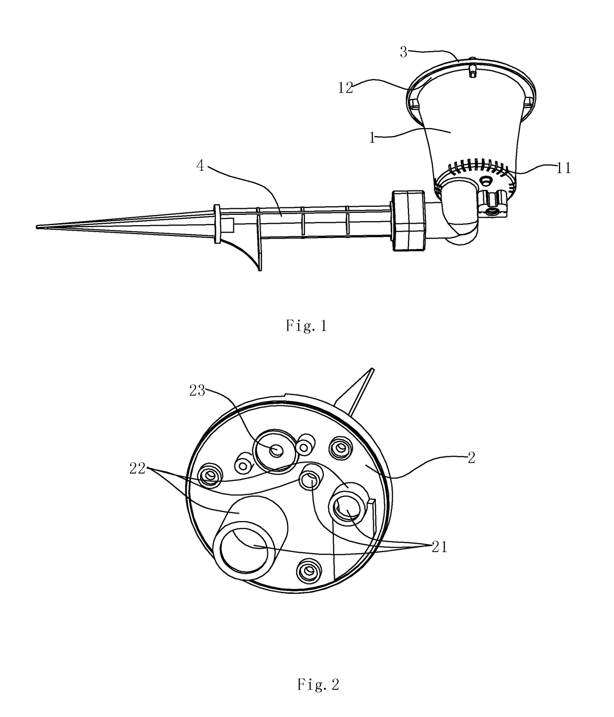
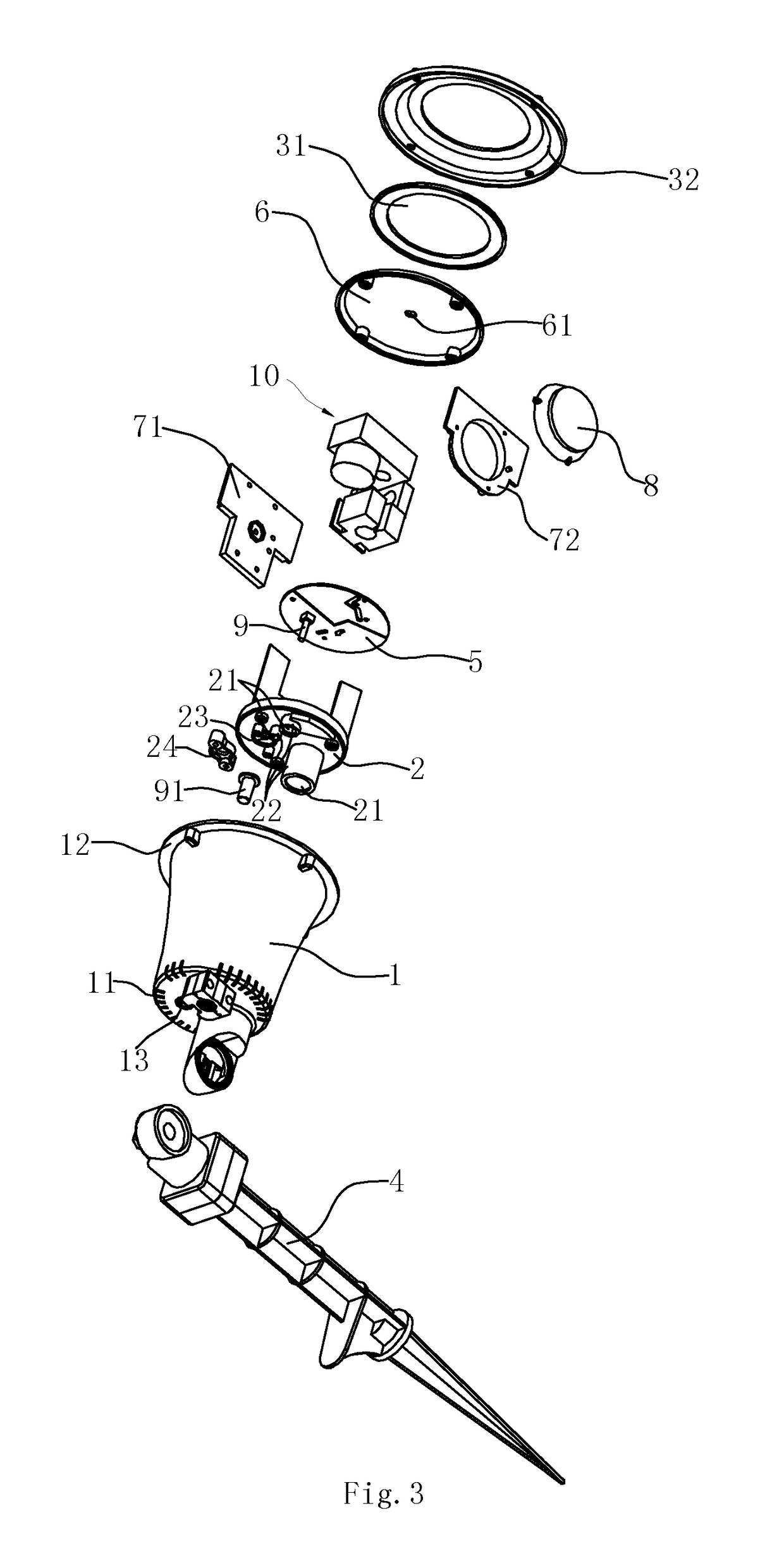
[0018]FIG. 1-FIG. 3 show a preferred embodiment of the outdoor laser lamp. The outdoor laser lamp comprises a housing 1, a laser 10, a circuit board 5, a fan 8 and a lower mounting plate 2 all disposed inside the housing 1.

[0019]To adjust the irradiation angle of the laser lamp conveniently, a rotatable mounting rod 4 is connected to the bottom of the housing 1.

[0020]The periphery of the lower mounting plate 2 is hermetically in contact with an inner wall of the housing 1, the lower mounting plate 2 partitions the housing 1 into two spaces, and the laser 10, the circuit board 5 and the fan 8 are disposed inside the housing 1. The laser, the circuit board 5 and the fan 8 are located between the lower mounting plate 2 and the cover body 3.

[0021]An upper mounting plate 6 is disposed under the cover body ...


PUM


Abstract

An outdoor laser lamp includes a housing, a laser and a circuit board disposed inside the housing, and a lower mounting plate. A periphery of the lower mounting plate is in contact with an inner wall of the housing, a laser and a circuit board are located between the lower mounting plate and the top of the housing. Air vents are on the bottom of the housing; through holes are on the lower mounting plate, a raised ring wall surrounds each through hole and extends towards the bottom of the housing. The laser lamp realizes air circulation between outside air and the interior of the housing, realizes rapid heat dispersion of the laser lamp to ensure the functionality of the laser lamp. Additionally, it prevents water entering the space where the circuit board is arranged, to avoid the influence on the internal circuits by water.

Description

RELATE APPLICATIONS[0001]This application is a national phase entrance of and claims benefit to PCT Application for an outdoor laser lamp, PCT / CN2015 / 000589, filed on Aug. 14, 2015, which claims benefit to Chinese Patent Application 201520069169.2, filed on Jan. 30, 2015. The specifications of both applications are incorporated here by this reference.FIELD OF THE INVENTION[0002]The present invention relates to an outdoor laser lamp having a cooling function.DESCRIPTION OF THE PRIOR ART[0003]Outdoor laser lamps are the first choice for scene decoration in outdoor activities. However, the outdoor laser lamps must be waterproof as they are to be used outdoor. At present, the outdoor laser lamps mostly employ the design of a fully-closed housing mechanism in order to be waterproof. However, during operation of a laser lamp of such a structure, heat generated by a laser head can not be dispersed effectively, and the temperature in the interior of the housing thus increases continuously. ...

Claims


Application Information

Patent Timeline
Patent Type & Authority Patents(United States)
IPC IPC(8): B60Q1/06F21S13/10G02B27/20F21V31/03F21S8/08F21S8/00F21V11/00F21V21/08B60Q1/00F21V29/00B60Q3/00F21V23/04F21V21/30F21V29/67F21V29/508F21V29/507F21W131/10F21Y115/30
CPCF21V31/03F21S8/081F21V21/0824F21V21/30F21Y2115/30F21V29/507F21V29/508F21V29/67F21W2131/10F21V23/04
Inventor QIN, BINGJIANG, DEJUNCAI, MEIXING
Owner CHANGXING POTEK ELECTRONICS & TECH CO LTD
Why Eureka
Try Eureka