Elastic wave resonator, elastic wave filter, duplexer, and elastic wave device

a technology of elastic wave resonator and elastic wave filter, which is applied in the direction of piezoelectric/electrostrictive/magnetostrictive devices, electrical apparatus, impedence networks, etc., can solve problems such as the decrease of signal linearity, and achieve the effect of reducing or preventing the occurrence of non-linear signals

Active Publication Date: 2018-08-28
MURATA MFG CO LTD
View PDF12 Cites 1 Cited by
  • Summary
  • Abstract
  • Description
  • Claims
  • Application Information

AI Technical Summary

Benefits of technology

[0007]Preferred embodiments of the present invention provide an elastic wave resonator that significantly reduces or prevents the occurrence of non-linear signals, as well as an elastic wave filter and a duplexer including such an elastic wave resonator.

Problems solved by technology

However, forming the interdigital transducer electrode from Al film as in the elastic wave resonator according to Japanese Unexamined Patent Application Publication No. 2-295212 has caused a decrease in the linearity of signals.

Method used


Image

  • Elastic wave resonator, elastic wave filter, duplexer, and elastic wave device
  • Elastic wave resonator, elastic wave filter, duplexer, and elastic wave device
  • Elastic wave resonator, elastic wave filter, duplexer, and elastic wave device

Examples


first preferred embodiment

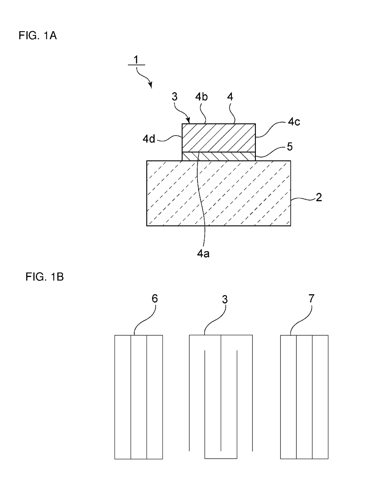
[0037]FIG. 1A is a schematic elevational cross-sectional view of an elastic wave resonator according to a first preferred embodiment of the present invention, and FIG. 1B is a schematic plan view illustrating the electrode structure thereof. An elastic wave resonator 1 includes a piezoelectric substrate 2. An interdigital transducer electrode 3 is laminated onto a main surface of the piezoelectric substrate 2. The interdigital transducer electrode 3 includes first and second electrode layers 4 and 5. More specifically, the interdigital transducer electrode 3 includes a second electrode layer 5 provided on the piezoelectric substrate 2, and a first electrode layer 4 laminated onto the second electrode layer 5.

[0038]The first electrode layer 4 includes first and second main surfaces 4a and 4b and first and second side surfaces 4c and 4d. The first main surface 4a of the first electrode layer 4 is located on the piezoelectric substrate 2 side. The first main surface 4a of the first ele...

second preferred embodiment

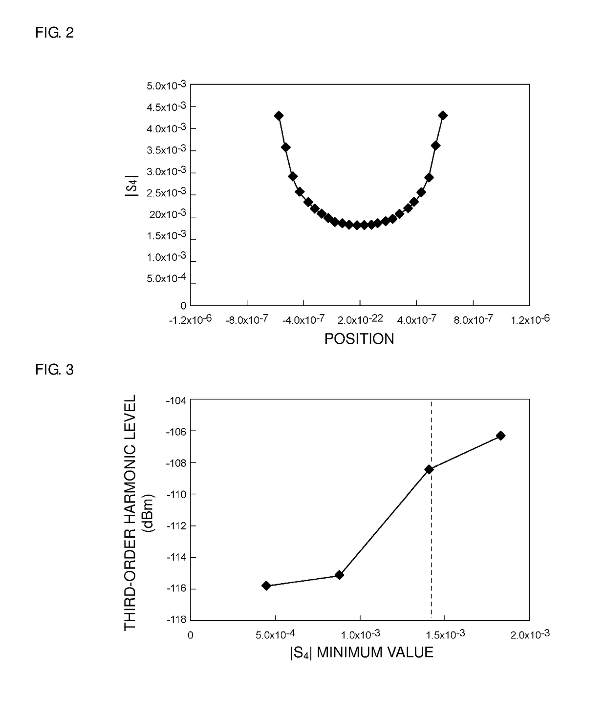
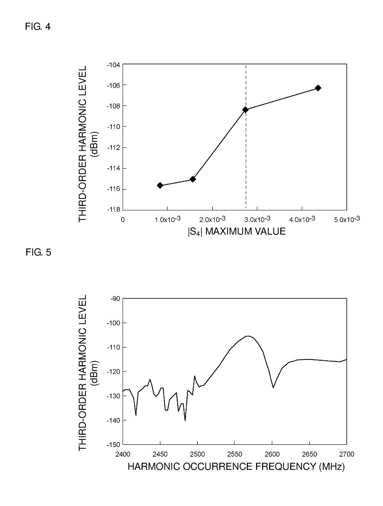
[0055]In the first preferred embodiment, the minimum value of the absolute value of the distortion S4 component in the first main surface 4a is preferably about 1.4×10⁻³ or less, for example. In a second preferred embodiment of the present invention, the maximum value of the absolute value of the distortion S4 component in the first main surface 4a preferably is about 2.7×10⁻³ or less, for example. The second preferred embodiment is preferably the same or substantially the same as the first preferred embodiment in other respects. The maximum value of the absolute value of the distortion S4 component will be described in detail hereinafter with reference to FIG. 4.

[0056]FIG. 4 is a graph illustrating a relationship between the maximum value of the absolute value (|S4|) of the distortion component S4 in the first main surface 4a of the first electrode layer 4, and a peak level of a third-order harmonic. In FIG. 4, the maximum value of |S4| is the maximum value of |S4| indicated in FIG...

third preferred embodiment

[0060]FIG. 6 is a schematic elevational cross-sectional view of an elastic wave resonator according to a third preferred embodiment of the present invention. In an elastic wave resonator 21, portions of the first and second side surfaces 4c and 4d of the first electrode layer 4 make contact with the second electrode layer 5.

[0061]In the elastic wave resonator 21, the minimum value of the absolute value of the distortion S4 component preferably is about 1.4×10⁻³ or less at the portions where the first and second side surfaces 4c and 4d of the first electrode layer 4 make contact with the second electrode layer 5. Alternatively, the maximum value of the absolute value of the distortion S4 component is about 2.7×10⁻³ or less at the portions where the first and second side surfaces 4c and 4d of the first electrode layer 4 make contact with the second electrode layer 5. The third preferred embodiment is preferably the same or substantially the same as the first preferred embodiment in ot...


PUM


Abstract

An elastic wave resonator includes an interdigital transducer electrode provided on a piezoelectric substrate and including a first electrode layer made of Al or an alloy with Al as its primary component and including a first main surface on a side where the piezoelectric substrate is located and a second main surface on the opposite side from the first main surface. An SH wave is used as a propagated elastic wave. When a resonant frequency of the elastic wave resonator is fr and an anti-resonant frequency of the elastic wave resonator is fa, a minimum value of an absolute value of a distortion component in the first main surface calculated through a two-dimensional finite element method is about 1.4×10⁻³ or less at a frequency f expressed as:f=fr+0.06×bw, where bw is fa−fr.

Description

CROSS REFERENCE TO RELATED APPLICATIONS[0001]This application claims the benefit of priority to Japanese Patent Application No. 2014-243184 filed on Dec. 1, 2014 and is a Continuation Application of PCT Application No. PCT / JP2015 / 082103 filed on Nov. 16, 2015. The entire contents of each application are hereby incorporated herein by reference.BACKGROUND OF THE INVENTION[0002]1. Field of the Invention[0003]The present invention relates to an elastic wave resonator in which an interdigital transducer electrode is provided on a piezoelectric substrate, and to an elastic wave filter and duplexer including such an elastic wave resonator.[0004]2. Description of the Related Art[0005]Conventionally, elastic wave resonators are widely used as resonators defining band-pass filters included in cellular phones and the like. Japanese Unexamined Patent Application Publication No. 2-295212, for example, discloses an elastic wave resonator including a piezoelectric substrate and an interdigital tra...

Claims


Application Information

Patent Timeline
Patent Type & Authority Patents(United States)
IPC IPC(8): H03H9/64H03H9/72H01L41/047H03H9/25H01L41/107
CPCH01L41/0477H01L41/107H03H9/725H03H9/64H03H9/25H03H9/02818H03H9/14541H03H9/145H03H9/72H10N30/877H10N30/40
Inventor NAKAGAWA, RYO
Owner MURATA MFG CO LTD
Why Eureka
Try Eureka