Elastic wave resonator, elastic wave filter, duplexer, and elastic wave device
a technology of elastic wave resonator and elastic wave filter, which is applied in the direction of piezoelectric/electrostrictive/magnetostrictive devices, electrical apparatus, impedence networks, etc., can solve problems such as the decrease of signal linearity, and achieve the effect of reducing or preventing the occurrence of non-linear signals
- Summary
- Abstract
- Description
- Claims
- Application Information
AI Technical Summary
Benefits of technology
Problems solved by technology
Method used
Image
Examples
first preferred embodiment
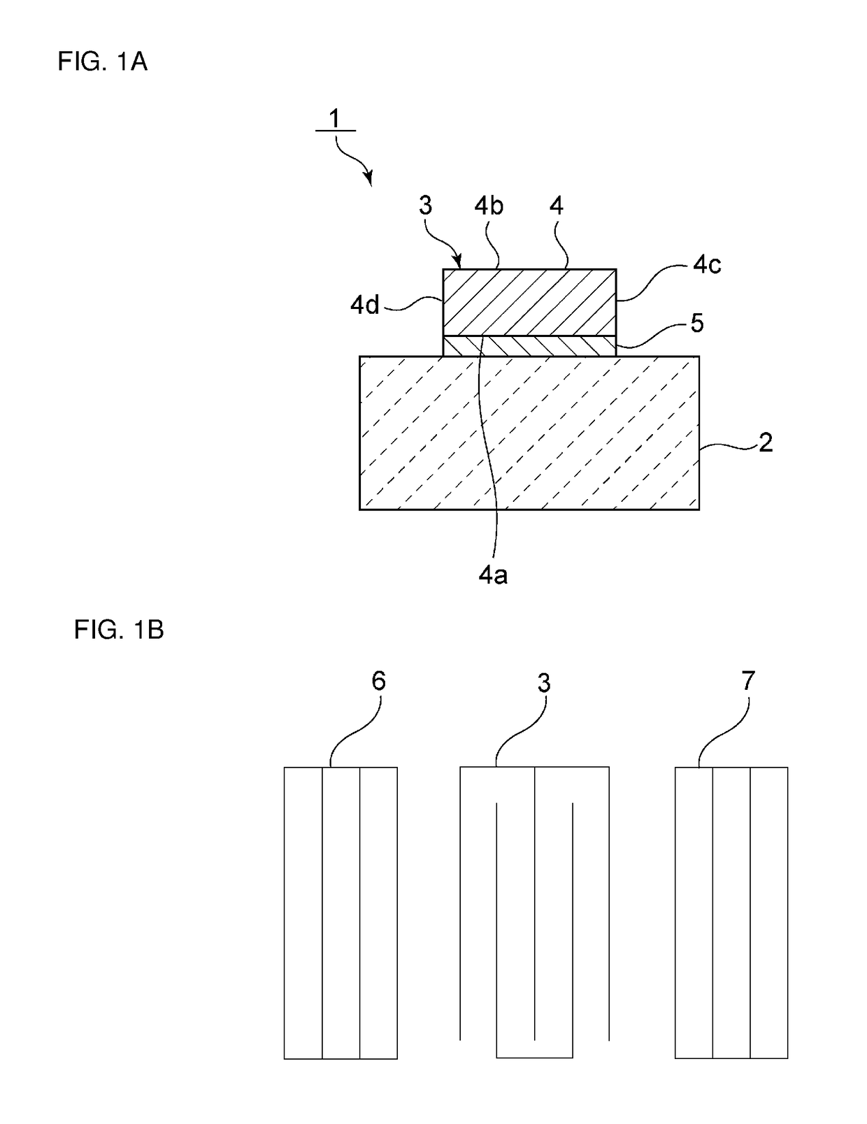
[0037]FIG. 1A is a schematic elevational cross-sectional view of an elastic wave resonator according to a first preferred embodiment of the present invention, and FIG. 1B is a schematic plan view illustrating the electrode structure thereof. An elastic wave resonator 1 includes a piezoelectric substrate 2. An interdigital transducer electrode 3 is laminated onto a main surface of the piezoelectric substrate 2. The interdigital transducer electrode 3 includes first and second electrode layers 4 and 5. More specifically, the interdigital transducer electrode 3 includes a second electrode layer 5 provided on the piezoelectric substrate 2, and a first electrode layer 4 laminated onto the second electrode layer 5.
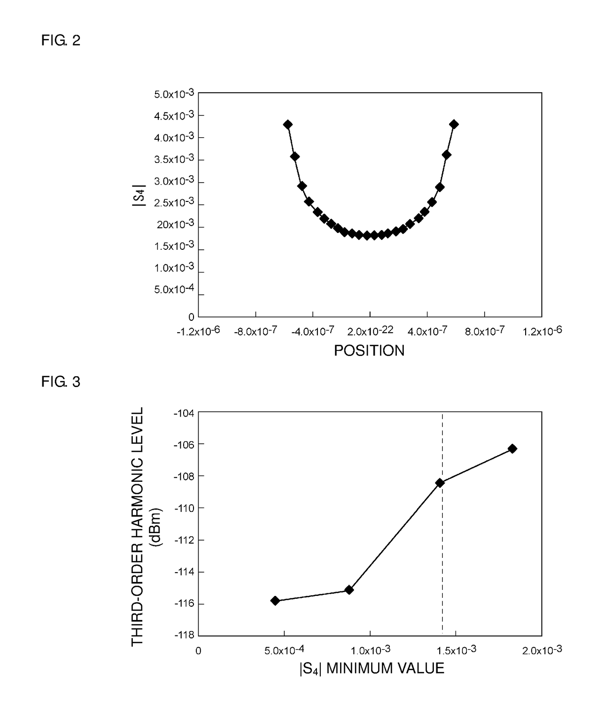
[0038]The first electrode layer 4 includes first and second main surfaces 4a and 4b and first and second side surfaces 4c and 4d. The first main surface 4a of the first electrode layer 4 is located on the piezoelectric substrate 2 side. The first main surface 4a of the first ele...
second preferred embodiment
[0055]In the first preferred embodiment, the minimum value of the absolute value of the distortion S4 component in the first main surface 4a is preferably about 1.4×10⁻³ or less, for example. In a second preferred embodiment of the present invention, the maximum value of the absolute value of the distortion S4 component in the first main surface 4a preferably is about 2.7×10⁻³ or less, for example. The second preferred embodiment is preferably the same or substantially the same as the first preferred embodiment in other respects. The maximum value of the absolute value of the distortion S4 component will be described in detail hereinafter with reference to FIG. 4.
[0056]FIG. 4 is a graph illustrating a relationship between the maximum value of the absolute value (|S4|) of the distortion component S4 in the first main surface 4a of the first electrode layer 4, and a peak level of a third-order harmonic. In FIG. 4, the maximum value of |S4| is the maximum value of |S4| indicated in FIG...
third preferred embodiment
[0060]FIG. 6 is a schematic elevational cross-sectional view of an elastic wave resonator according to a third preferred embodiment of the present invention. In an elastic wave resonator 21, portions of the first and second side surfaces 4c and 4d of the first electrode layer 4 make contact with the second electrode layer 5.
[0061]In the elastic wave resonator 21, the minimum value of the absolute value of the distortion S4 component preferably is about 1.4×10⁻³ or less at the portions where the first and second side surfaces 4c and 4d of the first electrode layer 4 make contact with the second electrode layer 5. Alternatively, the maximum value of the absolute value of the distortion S4 component is about 2.7×10⁻³ or less at the portions where the first and second side surfaces 4c and 4d of the first electrode layer 4 make contact with the second electrode layer 5. The third preferred embodiment is preferably the same or substantially the same as the first preferred embodiment in ot...
PUM
 Abstract
Description
Claims
Application Information
 - R&D
- Intellectual Property
- Life Sciences
- Materials
- Tech Scout
- Unparalleled Data Quality
- Higher Quality Content
- 60% Fewer Hallucinations
Browse by: Latest US Patents, China's latest patents, Technical Efficacy Thesaurus, Application Domain, Technology Topic, Popular Technical Reports.
© 2025 PatSnap. All rights reserved.Legal|Privacy policy|Modern Slavery Act Transparency Statement|Sitemap|About US| Contact US: help@patsnap.com


