
Unloading systems

a technology of unloading system and unloading vehicle, which is applied in the direction of loading/unloading, agriculture, agricultural tools and machines, etc., can solve the problems of crop loss, reduce reduce the amount of material, and increase the speed of the collection vehicle

Active Publication Date: 2018-09-04
BLUE LEAF I P INC
View PDF44 Cites 25 Cited by
  • Summary
  • Abstract
  • Description
  • Claims
  • Application Information

AI Technical Summary

Benefits of technology

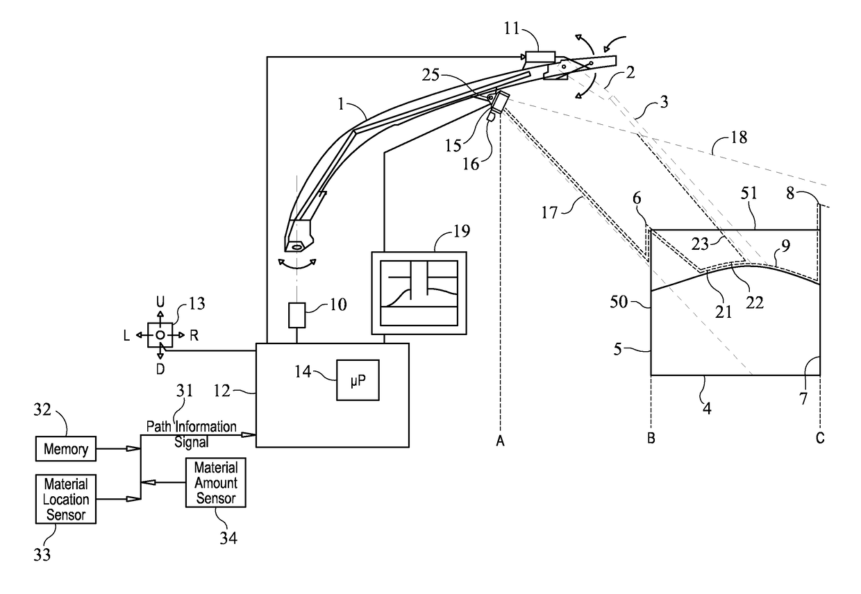
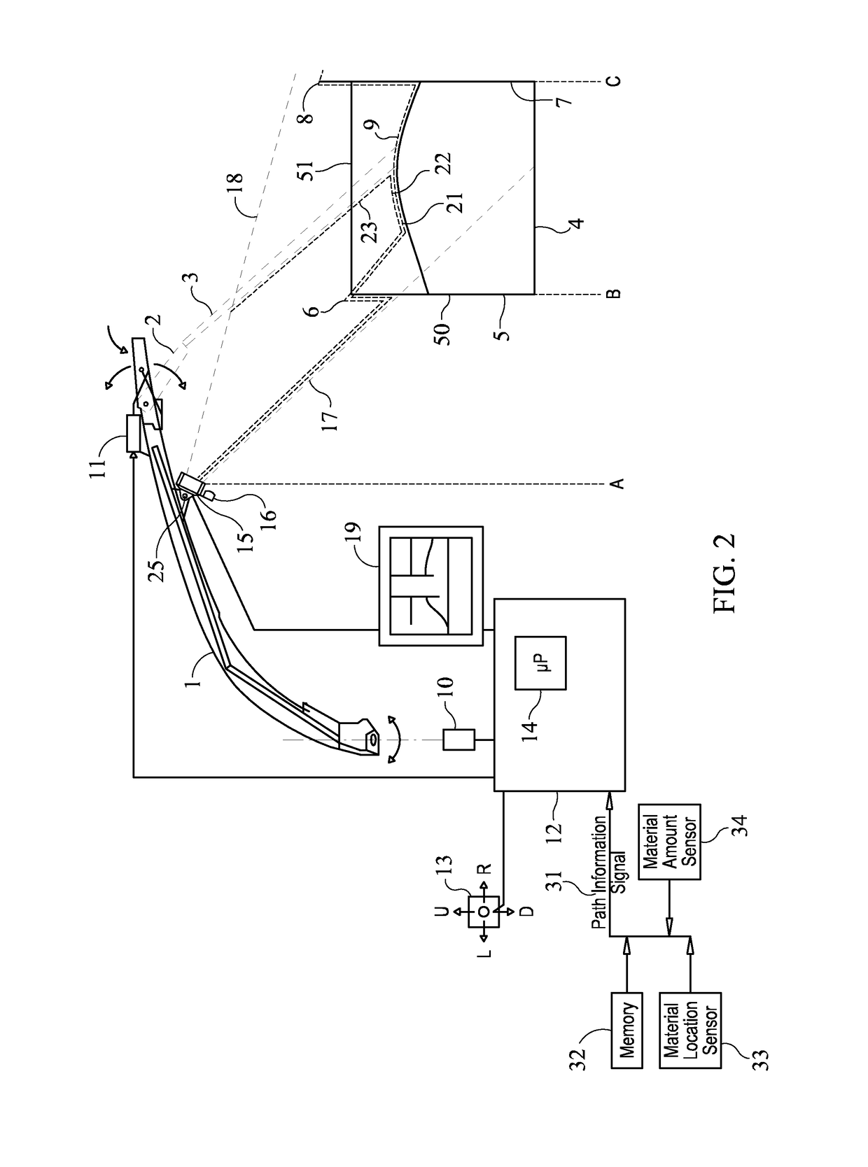
[0009]In this way, the unloading system can be automatically controlled such that characteristics of the path that will affect the unloading of material, can be taken into account quickly and efficiently when directing the material from the unloading apparatus to the container. This enables modulation of the setting of the attribute in a proactive way, before the changes in relative movement between the unloading and unloading vehicles caused by a feature of the upcoming path show from the image data. This can reduce spillage of the material from the container.
[0021]increase the speed of the collection vehicle and / or set an attribute of the unloading apparatus in order to direct the material from the unloading apparatus to a region of the container that is further forwards, if the path information signal is indicative of a reducing amount of material that is to be collected, and / or
[0022]decrease the speed of the collection vehicle and / or set an attribute of the unloading apparatus in order to direct the material from the unloading apparatus to a region of the container that is further backwards, if the path information signal is indicative of an increasing amount of material that is to be collected.
[0037]The method may comprise increasing the speed of the collection vehicle and / or setting an attribute of the unloading apparatus in order to direct the material from the unloading apparatus to a region of the container that is further forwards, if the path information signal is indicative of a reducing amount of material that is to be collected.
[0038]The method may comprise decreasing the speed of the collection vehicle and / or setting an attribute of the unloading apparatus in order to direct the material from the unloading apparatus to a region of the container that is further backwards, if the path information signal is indicative of an increasing amount of material that is to be collected.

Problems solved by technology

These prior art systems react to changes in the actual images and may not always have sufficient time for realigning the spout when one or more harvesting or field conditions suddenly change, such that some crop may be lost.

Method used


Image

  • Unloading systems
  • Unloading systems
  • Unloading systems

Examples


Embodiment Construction

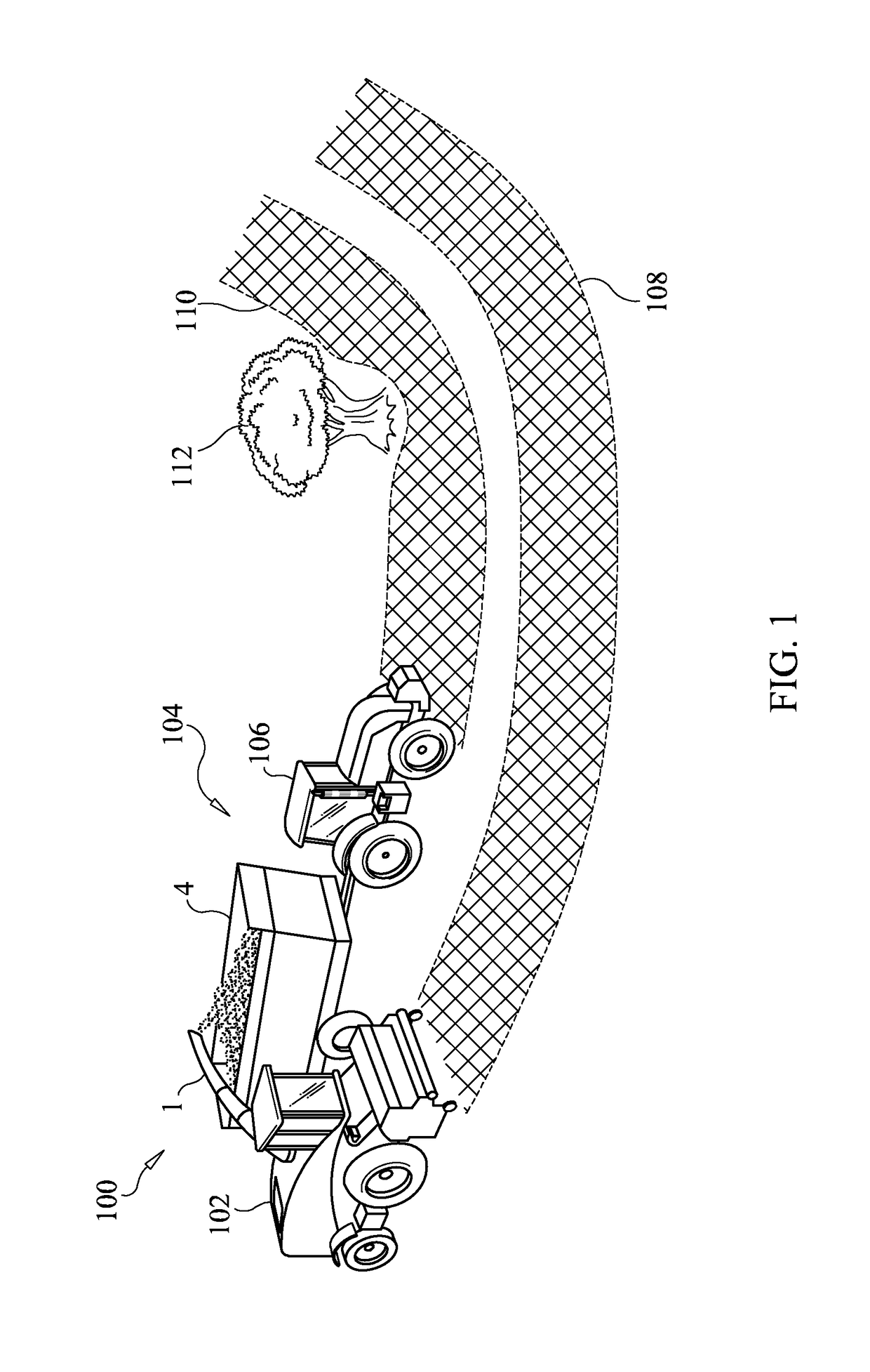
[0048]FIGS. 1 and 2 are examples of an unloading system in the agricultural industry. It will be appreciated from the description that follows that examples disclosed herein can also be used in other industries, for example in construction.

[0049]FIG. 1 shows schematically an unloading system 100. The unloading system 100 comprises an unloading vehicle 102, which in this example is an agricultural harvesting machine such as a forage harvester or a combine harvester. The agricultural harvesting machine 102 has an unloading apparatus 1, which in this example is a discharge spout. Further details of the discharge spout 1 are provided below with reference to FIG. 2. The unloading system 100 also has a collection vehicle 104 having a container 4 for receiving material that has been unloaded by the unloading vehicle 102. In this example, the collection vehicle is a tractor 106 that tows the container 4 and the material is a crop. In other examples the container may be part of the collectio...


PUM


Abstract

A controller for an unloading system. The unloading system comprises an unloading vehicle having an unloading apparatus and a collection vehicle having a container. The unloading apparatus is configured to direct material to the container driven in the vicinity of the unloading vehicle. The controller is configured to: receive image data representative of at least a portion of the container; receive a path information signal representative of a path that is to be followed by the unloading vehicle or the collection vehicle; and set an attribute of the unloading apparatus, the unloading vehicle, or the collection vehicle in accordance with the image data and the path information signal in order to direct the material from the unloading apparatus to the container.

Description

CROSS REFERENCE TO RELATED APPLICATIONS[0001]This application is the National Stage of International Application No. PCT / EP2014 / 073106 filed on Oct. 28, 2014, which claims priority to Belgian Application No. 2013 / 0725 filed Oct. 28, 2013, each of which applications is incorporated herein by reference in its entirety.FIELD OF THE INVENTION[0002]The present disclosure relates to unloading systems that include an unloading vehicle such as a forage harvester or a combine harvester, and in particular to controllers for such unloading systems.BACKGROUND OF THE INVENTION[0003]In forage harvesters of the above type, control of the spout position and of the position of a pivotable end portion (flap) of the spout on the basis of camera images is known in the art. Patent publication WO-A-2011 / 101458 describes a system in which a 3D camera is arranged on the discharge spout. The camera takes images of the container driving next to the machine. These images define at least two vertical strips. A...

Claims


Application Information

Patent Timeline
Patent Type & Authority Patents(United States)
IPC IPC(8): A01D90/10A01D90/12A01D43/08B65G67/24
CPCA01D90/10B65G67/24A01D90/12A01D43/087
Inventor BYTTEBIER, WARD M. R.DEPESTEL, BERNARD E. D.VANYSACKER, PIETERVIAENE, KAREL M. C.
Owner BLUE LEAF I P INC
Learn More