Minimally invasive screw extension assembly

a screw extension and minimally invasive technology, applied in the field of minimally invasive screw extension assembly, can solve the problems of surgeons aligning fixation rods, particularly difficult,

Active Publication Date: 2018-09-04
SPINAL ELEMENTS INC
View PDF21 Cites 5 Cited by
  • Summary
  • Abstract
  • Description
  • Claims
  • Application Information

AI Technical Summary

Benefits of technology

[0010]In one embodiment, the threads of the proximal end of the inner shaft has a pitch sufficient to allow the nut to auto-rotate, solely due to the weight of the nut, to abut the proximal end of the reducer and further rotation pushes the reducer inwardly to seat a rod in a rod seating position. The nut is preferably removable and separate from the outer shaft, this allows the rod reducer to fit easily over the assembled inner and outer shafts. The outer shaft has flats in the proximal portion and the locking knob has flats configured to align with the flats of the outer shaft when the locking knob is rotated to a locked position allowing the reducer with complimentary internal flats to non-rotationally move relative to the assembly as the nut pushes the reducer.

Problems solved by technology

One difficulty for the surgeon is aligning the fixation rods with the slotted rod receiving implants and moving the rod inwardly toward the slot.
This is particularly difficult when the implants need to be positioned to correct a preexisting misalignment.

Method used


Image

  • Minimally invasive screw extension assembly
  • Minimally invasive screw extension assembly
  • Minimally invasive screw extension assembly

Examples


Embodiment Construction

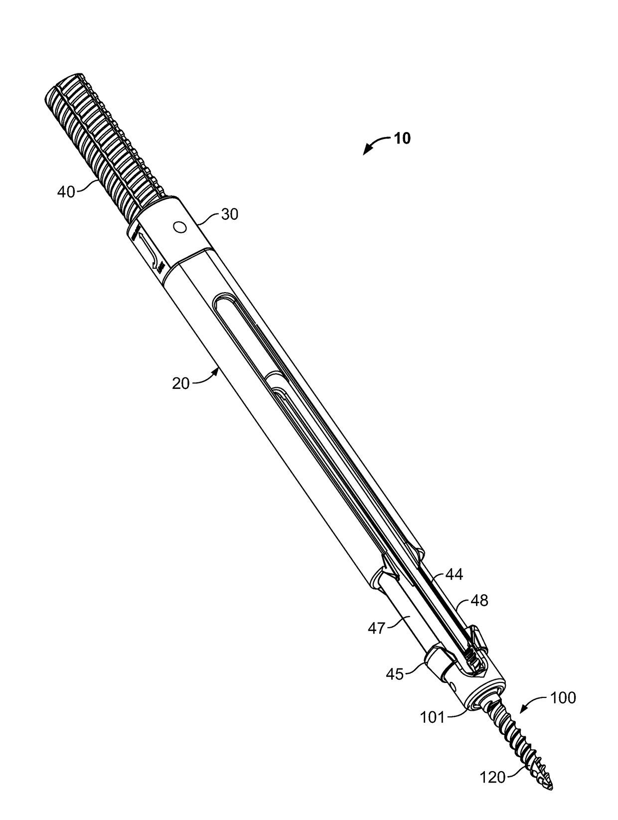
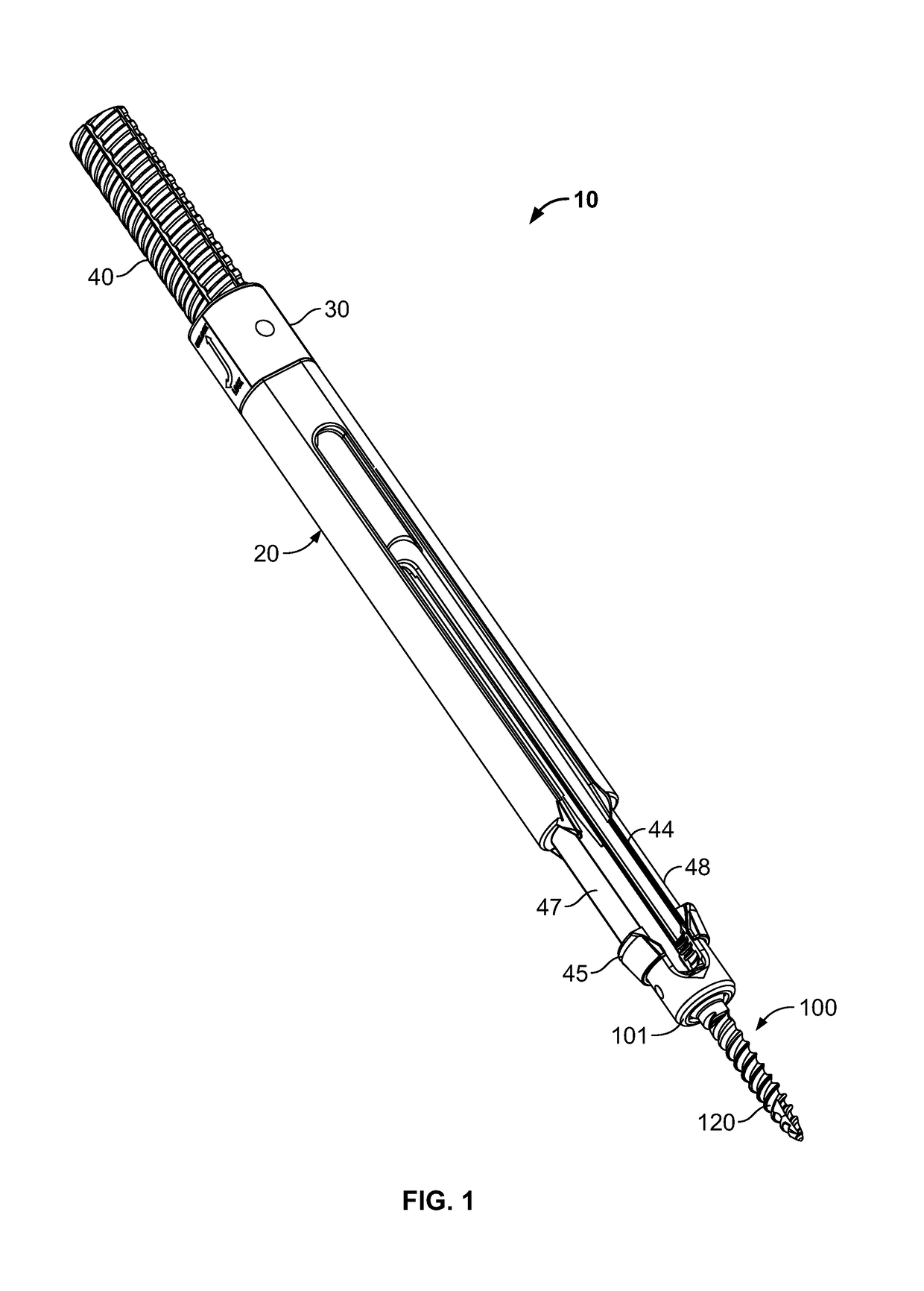
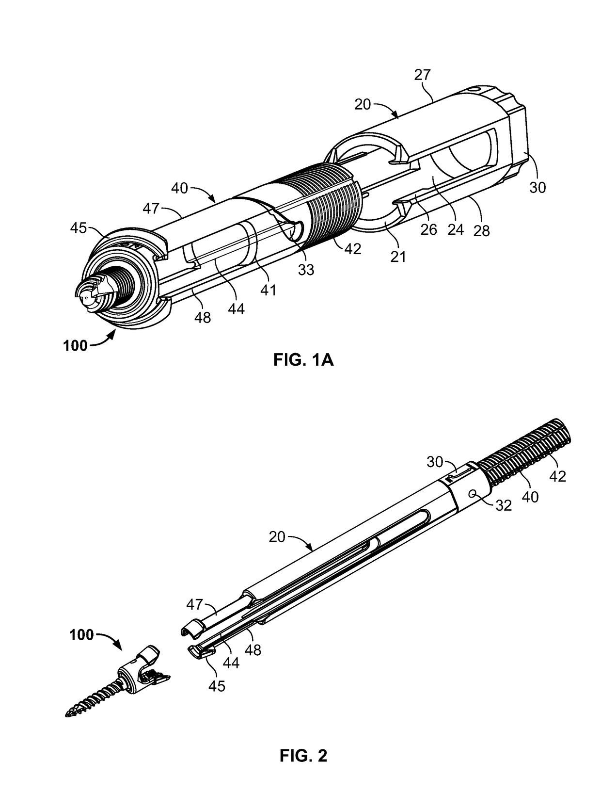
[0036]With reference to FIG. 1, a screw extension assembly 10 is illustrated. The screw extension assembly 10 has an outer shaft 20 and an inner shaft 40. As shown, at a distal end of the screw extension assembly 10 is a rod receiving implant 100. The rod receiving implant 100 has a rod holding element 101 and a bone or pedicle screw 120 extending from the base of the rod holding element 101. The rod holding element 101 is slotted and configured to receive a spinal rod. As shown in FIGS. 1 and 1A, the inner shaft 40 has slots 44 defining deflectable leg extensions 47, 48. The deflectable leg extensions 47, 48 have a distal end 45 configured to deflect and engage the rod holding element 101. The rod holding element 101 has a groove 109 configured to engage a projection 49 on the distal end 45 of the deflectable legs 47, 48, best shown in FIG. 3A.

[0037]With further reference to FIG. 1A, the outer shaft 20 has a proximal end with a rotatable locking knob 30 affixed thereto. The outer s...


PUM


Abstract

A screw extension assembly for use in minimally invasive spinal surgery, the assembly has an inner slotted shaft and an outer shaft, a rod reducer and a removable nut. The combination when assembled is configured to move a spinal fixation rod into a slotted rod receiving spinal implant where it is seated and affixed thereto. The screw extension assembly further has a locking knob rotationally coupled to a proximal end of the outer shaft, wherein the inner shaft has one or more cam grooves and the locking knob has a pin extending into and guided by said cam groove causing the outer shaft to translate longitudinally upon rotation of the locking knob relative to the inner shaft toward an engaged position locking the deflectable legs in the coupled position to the slotted rod receiving implant.

Description

TECHNICAL FIELD[0001]The present invention relates to a minimally invasive screw extension assembly for seating a fixation rod into a spinal fixation rod receiving implant and securing the seated fixation rod as part of a vertebral corrective surgery.BACKGROUND OF THE INVENTION[0002]Spinal surgeons are required to implant a variety of rods, screws and plates into the bony skeletal structure of the spine to correct a variety of misalignments and repair damage that exist between the vertebral bodies. A particularly useful procedure involves the placement of rod receiving spinal implants with pedicle screws into the vertebrae. These rod receiving implants commonly have a slotted “U” shaped body with a pedicle screw extending from the base of the slotted body. When the surgeon implants these devices in the bones along the portion of the spine to be corrected, he must then connect two or more of these implants using fixation rods. The fixation rods are typically solid round cylindrical m...

Claims


Application Information

Patent Timeline
Patent Type & Authority Patents(United States)
IPC IPC(8): A61B17/70A61B17/86A61B17/00
CPCA61B17/708A61B17/00234A61B17/8665A61B17/7086A61B17/7085
Inventor GUNN, JOSHUA DAVIDCAIN, DAVID BRETT
Owner SPINAL ELEMENTS INC
Why Eureka
Try Eureka