Assembly for loosening or tightening mechanical nuts (esp. wheel nuts)

a technology for tightening and mechanical nuts, which is applied in the direction of tyre parts, tyre repairing, vehicle components, etc., can solve the problems of damage or injury, inability to provide the initial force required, and inability to operate the assembly, so as to prevent the displacement of the socket arm

Inactive Publication Date: 2018-09-04
THE TRUSTEES FOR THE TIME BEING OF LE MOULIN TRUST
View PDF33 Cites 5 Cited by
  • Summary
  • Abstract
  • Description
  • Claims
  • Application Information

AI Technical Summary

Benefits of technology

[0010]a sliding hammer connected or connectable to a second end of the crank, thereby being operable to impart a rotational impact on the socket arm via the crank; and
[0015]The support structure may include a carrier member which defines the channel. The channel may be operable to permit rotation of the socket arm (e.g. as transmitted from the crank) but to prevent radial displacement of the socket arm.
[0024]If the sliding hammer and crank are relatively pivotable, the method may include orientating the sliding hammer and crank transversely to each other before actuating the sliding hammer, thereby to transmit maximum impact to the nut.

Problems solved by technology

Conventional wheel spanners or tyre irons can be inadequate for providing the initial force required to loosen a stubborn nut.
A difficulty with use of a slogging spanner is that it sometimes cannot fit onto a nut especially if the nut is recessed in a wheel rim and, upon being struck, it can be flung rapidly from the nut, possibly causing damage or injury.
A drawback of U.S. Pat. No. 5,109,739, in the opinion of the Inventors, is that operating the assembly can be difficult, requiring one hand to actuate the sliding hammer and the other hand both to support the assembly and to urge it against the wheel nut.

Method used


Image

  • Assembly for loosening or tightening mechanical nuts (esp. wheel nuts)
  • Assembly for loosening or tightening mechanical nuts (esp. wheel nuts)
  • Assembly for loosening or tightening mechanical nuts (esp. wheel nuts)

Examples


Embodiment Construction

[0042]The following description of the invention is provided as an enabling teaching of the invention. Those skilled in the relevant art will recognise that many changes can be made to the embodiment described, while still attaining the beneficial results of the present invention. It will also be apparent that some of the desired benefits of the present invention can be attained by selecting some of the features of the present invention without utilising other features. Accordingly, those skilled in the art will recognise that modifications and adaptations to the present invention are possible and can even be desirable in certain circumstances, and are a part of the present invention. Thus, the following description is provided as illustrative of the principles of the present invention and not a limitation thereof.

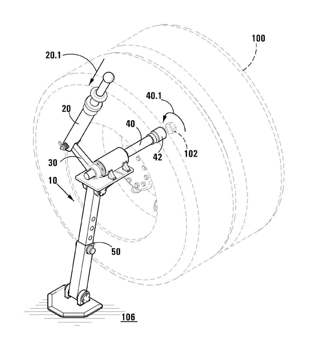
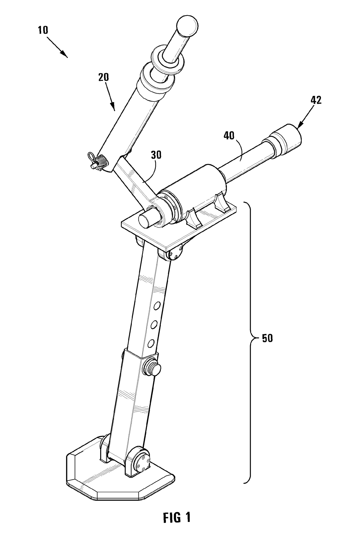
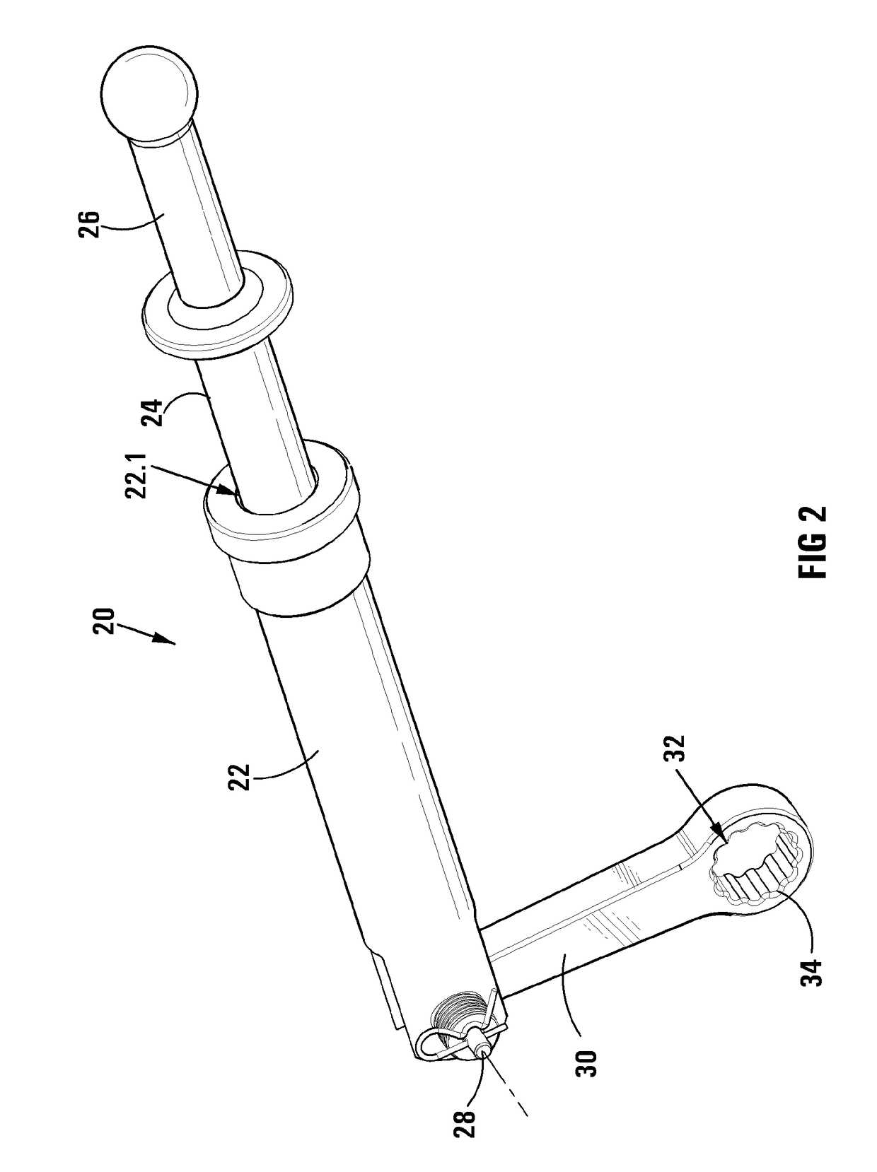
[0043]Referring to FIGS. 1-3, reference numeral 10 generally indicates an assembly, in accordance with the invention, for loosening mechanical nuts. The example is further...


PUM


Abstract

An assembly (200) for loosening or tightening mechanical nuts includes a socket arm (40) defining a socket (42) at its distal end for engaging a mechanical nut (102); a crank (30) connected or connectable at its first end transversely to a proximate end of the socket arm (40); a sliding hammer (20) connected or connectable to a second end of the crank (30), thereby being operable to impart a rotational impact on the socket arm (40) via the crank (30); and a support structure (250) connected or connectable at its proximate end to one of the socket arm (40), crank (30), or sliding hammer (20) and defining at its remote end a support surface (260) operable to bear against an external structure (100) thereby to support the assembly (200) in use.

Description

CROSS REFERENCE TO RELATED APPLICATIONS[0001]This application is a U.S. national stage application of International Patent Application Ser. No. PCT / IB2013 / 059399, filed Oct. 16, 2013, which claims the benefit of and priority to ZA Application No. 2012 / 07897, filed Oct. 19, 2012. The entire disclosures of these two applications are hereby incorporated by reference in their entireties.FIELD OF INVENTION[0002]This invention relates to an assembly for loosening or tightening (and optionally torqueing of) mechanical nuts (esp. wheel nuts) and to a method of loosening mechanical nuts using such an assembly.BACKGROUND OF INVENTION[0003]The Inventors are well aware of how difficult it can be to loosen stubborn or seized mechanical nuts from a corresponding bolt shank. This is especially true for wheel nuts. Conventional wheel spanners or tyre irons can be inadequate for providing the initial force required to loosen a stubborn nut.[0004]The inventors are aware of slogging spanners which com...

Claims


Application Information

Patent Timeline
Patent Type & Authority Patents(United States)
IPC IPC(8): B60B29/00B25B19/00B25D1/16
CPCB60B29/005B60B29/007B25D1/16B25B19/00
Inventor COETZEE, HENDRIK BERNARDUSCOETZEE, RENIER
Owner THE TRUSTEES FOR THE TIME BEING OF LE MOULIN TRUST
Why Eureka
Try Eureka