Compressor having improved sealing assembly

Inactive Publication Date: 2011-10-11
EMERSON CLIMATE TECH INC
View PDF31 Cites 2 Cited by
  • Summary
  • Abstract
  • Description
  • Claims
  • Application Information

AI Technical Summary

Benefits of technology

A compressor may alternatively include a shell and a bearing housing assembly located within the shell and secured relative thereto. A compression mechanism may be supported within the shell on the bearing housing assembly and may include a first discharge passage. A partition may extend over the compression mechanism and may include a second discharge passage in communication with the first discharge passage, the partition being fixed to the shell and abutting an axial end surface of the bearing housing assembly to control a maximum axial distance between the partition and the compression mechanism. A first annular seal may be located in a discharge pressure region of the compressor and may be disposed around the first and second discharge openings and sealingly engaged with the compression mechanism and

Problems solved by technology

During compressor operation, pressure fluctuations may cause the sealing arrangement to be displaced, resulting in a leak path being form

Method used


Image

  • Compressor having improved sealing assembly
  • Compressor having improved sealing assembly
  • Compressor having improved sealing assembly

Examples


Embodiment Construction

Example embodiments will now be described more fully with reference to the accompanying drawings.

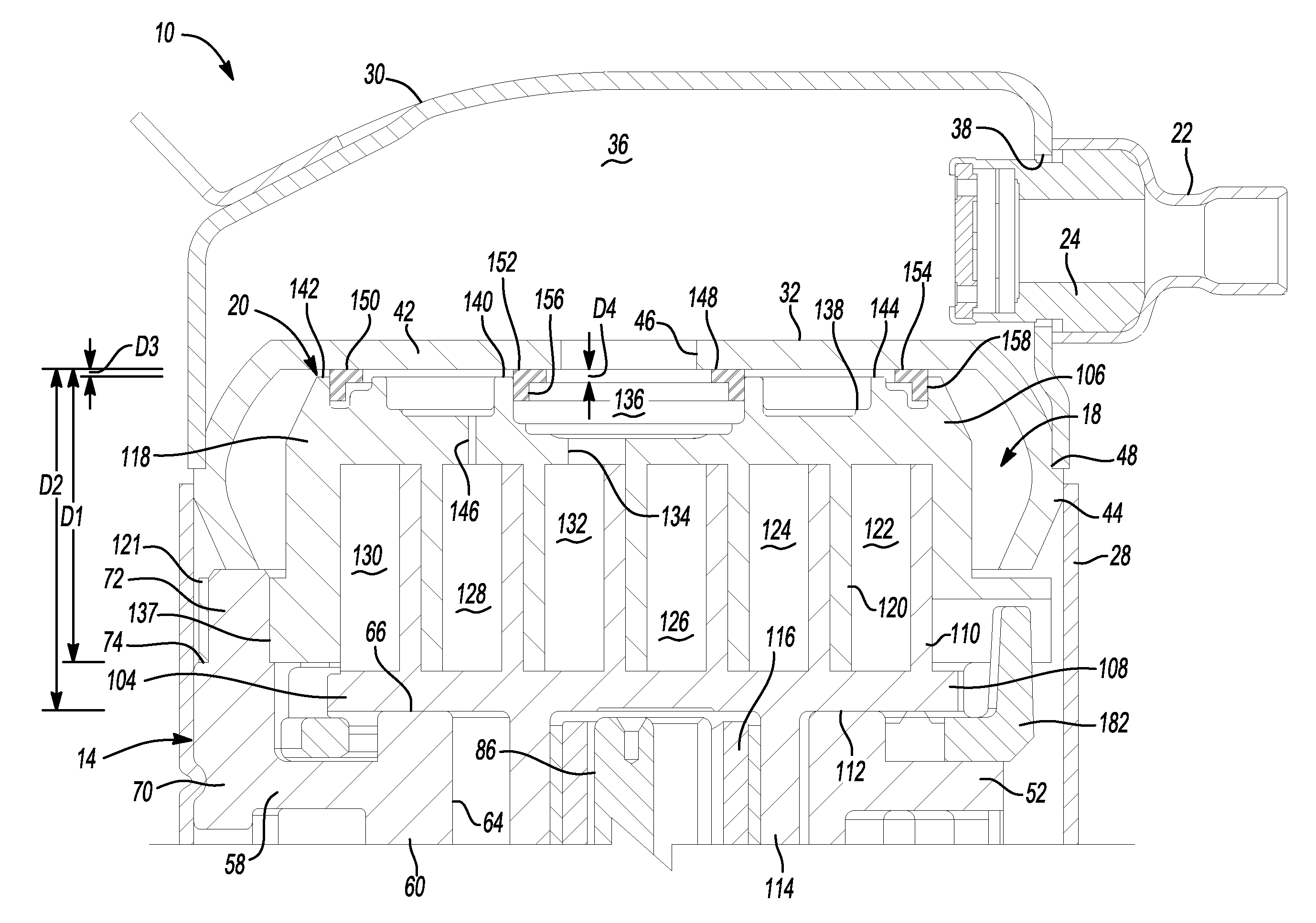
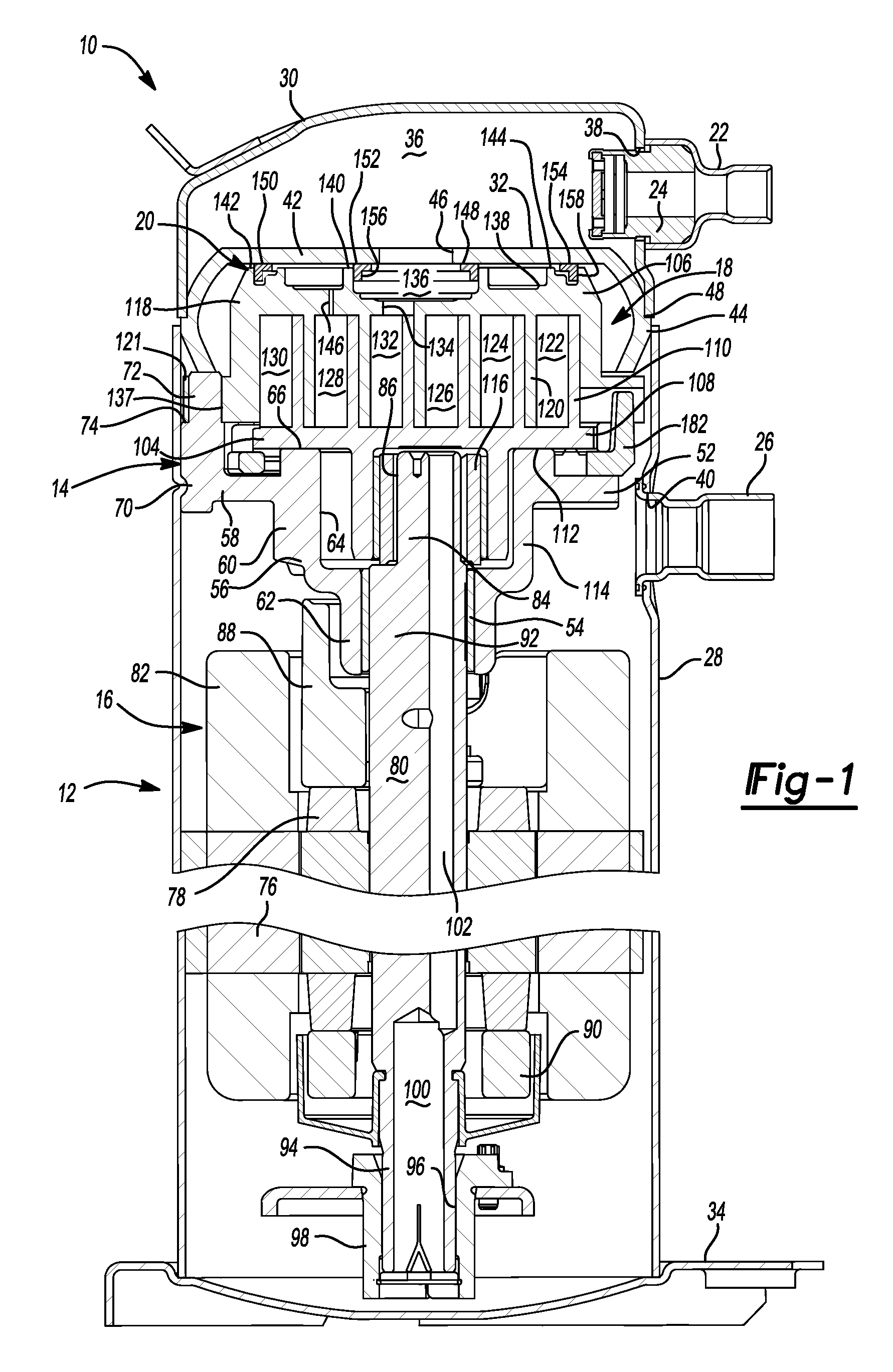
The present teachings are suitable for incorporation in many different types of scroll and rotary compressors, including hermetic machines, open drive machines and non-hermetic machines. For exemplary purposes, a compressor 10 is shown as a hermetic scroll refrigerant-compressor of the low-side type, i.e., where the motor and compressor are cooled by suction gas in the hermetic shell, as illustrated in the vertical section shown in FIG. 1.

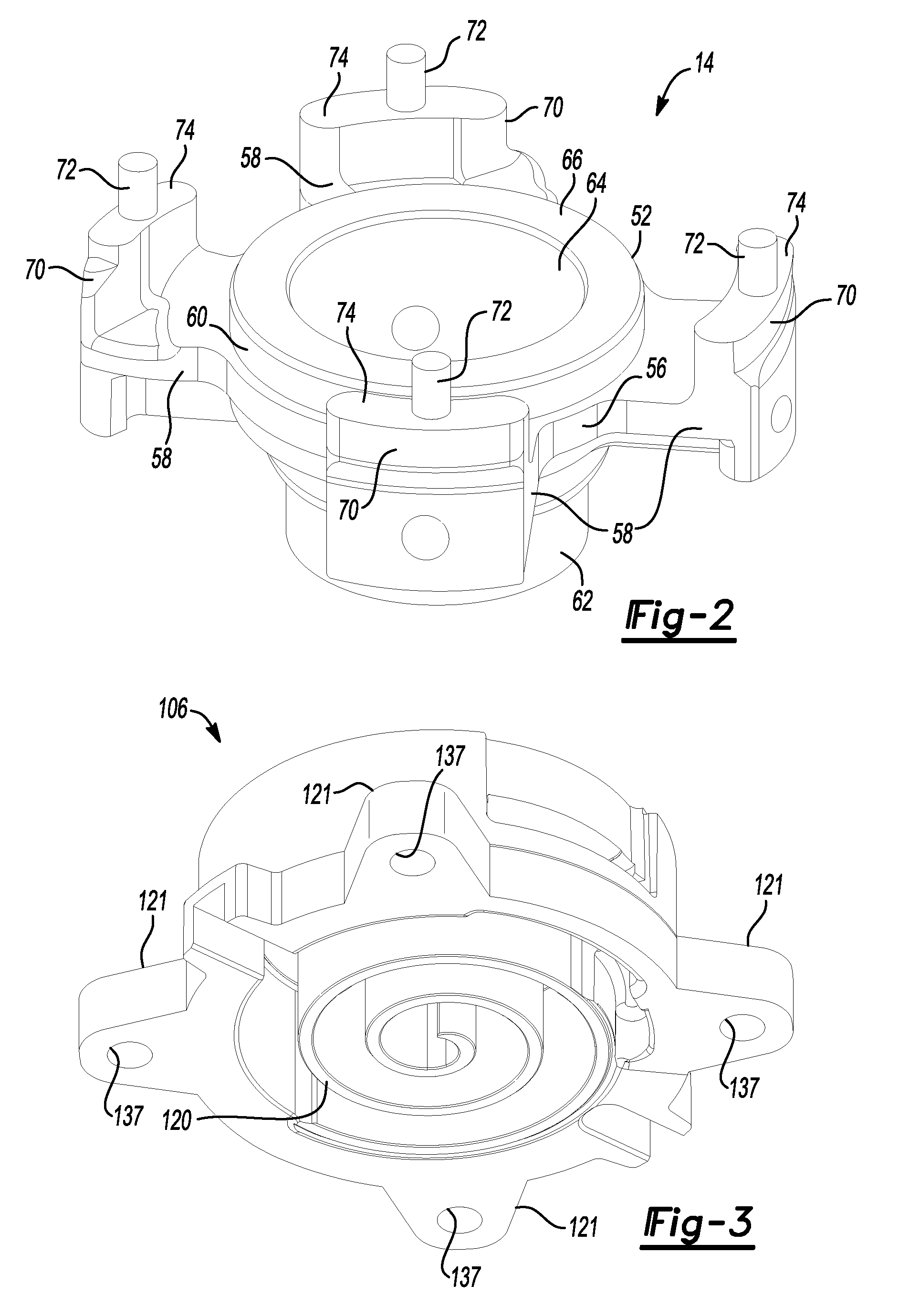
With reference to FIGS. 1 and 4, compressor 10 may include a hermetic shell assembly 12, a main bearing housing assembly 14, a motor assembly 16, a compression mechanism 18, a seal assembly 20, a refrigerant discharge fitting 22, a discharge valve assembly 24, and a suction gas inlet fitting 26. Shell assembly 12 may house main bearing housing assembly 14, motor assembly 16, and compression mechanism 18.

Shell assembly 12 may include a cylindrical shell ...


PUM


Abstract

A compressor may include a shell, a bearing housing assembly located within and secured to the shell, a compression mechanism supported on the bearing housing assembly, a partition extending over the compression mechanism, and an annular seal assembly. The partition may be fixed to the shell and may abut an axial end surface of the bearing housing assembly to control a maximum axial distance between the partition and the compression mechanism. The annular seal may be sealingly engaged with the compression mechanism and the bearing housing assembly and may have a generally L-shaped cross-section including a first leg extending generally laterally between the compression mechanism and the partition. The first leg may have an axial thickness that is greater than the maximum axial distance.

Description

FIELDThe present disclosure relates to compressors, and more specifically to a seal arrangement for a compressor.BACKGROUNDThis section provides background information related to the present disclosure which is not necessarily prior art.Compressors may include a sealing arrangement to isolate differing pressure regions from one another. During compressor operation, pressure fluctuations may cause the sealing arrangement to be displaced, resulting in a leak path being formed between the differing pressure regions. More significant pressure fluctuations may result in a seal being deformed or otherwise damaged.SUMMARYThis section provides a general summary of the disclosure, and is not a comprehensive disclosure of its full scope or all of its features.A compressor may include a shell, a bearing housing assembly located within and secured to the shell, a compression mechanism supported on the bearing housing assembly, a partition extending over the compression mechanism, and an annular...

Claims


Application Information

Patent Timeline
IPC IPC(8): F04C18/04F01C1/04F16J9/12F01C19/00
CPCF04C18/0215F04C23/008F04C27/001
Inventor STOVER, ROBERT C.
Owner EMERSON CLIMATE TECH INC
Why Eureka
Try Eureka