
C type grounding clamp

A grounding clip and grounding electrode technology, applied in the field of welding, cutting and electroplating, can solve problems such as poor contact, heating of contact parts, fire, etc., and achieve the effect of not easy to pull off and increase the coefficient of friction

Active Publication Date: 2016-01-06
马春辉
View PDF4 Cites 2 Cited by
  • Summary
  • Abstract
  • Description
  • Claims
  • Application Information

AI Technical Summary

Problems solved by technology

[0002] At present, the C-type grounding clamps sold in the market are connected with the grounding cable and the C-type grounding clamp, and the C-type grounding clamp is connected with the workpiece, so that the entire C-type grounding clamp becomes a Conductive carrier; when the grounding cable is connected to the C-type grounding clamp, the traditional connection method is used, or the grounding cable is connected with one hole and two top wires, or the copper nose connected to the grounding cable is directly fixed on the grounding clamp with screws. Under the dual effects of vibration and thermal expansion and contraction, a virtual connection phenomenon will not take long, which will directly lead to heating of the contact part, which will affect the stability of the current output in the slightest, and cause fire hazards in the severe case; The C-type grounding clip is used as a conductive carrier. In order to achieve a good conductive effect, the entire C-type grounding clip is made of more expensive copper, which increases the cost; as the moving part, the screw rod has to also play a conductive role. Vibration and loosening caused by thermal expansion and contraction will cause poor contact between the screw screw and the C-shaped structural part in the conductive state, resulting in electrical corrosion damage, and the screw screw and the C-shaped structural part cannot be repaired after the electrical corrosion damage. Replacement separately becomes a veritable one-time product, which wastes social resources and increases the hidden danger of accidents

Method used


Image

  • C type grounding clamp
  • C type grounding clamp

Examples


Embodiment Construction

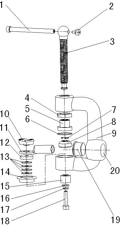
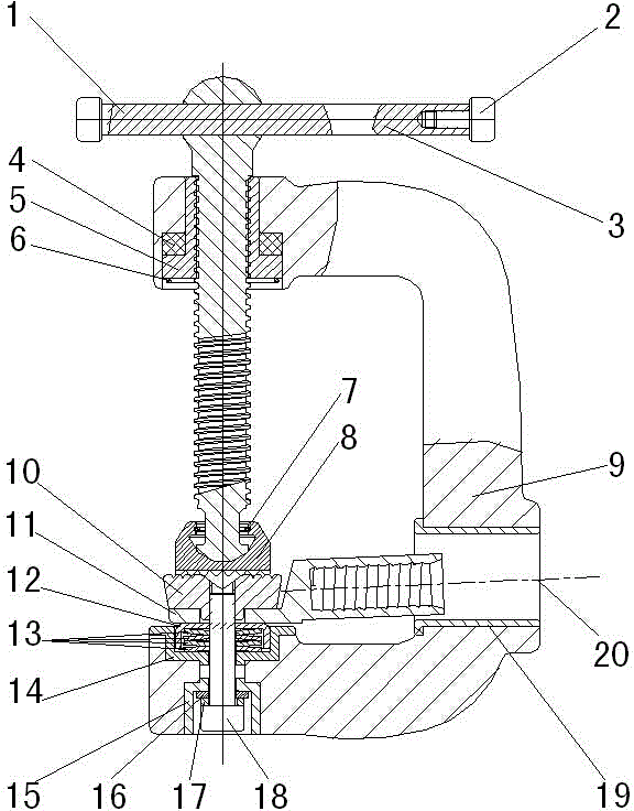
[0018] see figure 1 , figure 2 , this specific embodiment adopts the following technical solutions, a C-shaped grounding clamp, which consists of: a movable handle (1), a limit screw (2), a compression screw (3), an elastic material (4), a screw Sleeve (5), Screw Cover Circlip (6), Screw Circlip (7), Screw Seat (8), C-shaped Structural Part (9), Grounding Electrode (10), Connecting Nose (11), Anti Dust cover (12), elastic material (13), upper insulating seat (14), lower insulating seat (15), flat gasket (16), elastic gasket (17), fastening screw (18), protective cover ( 19), the upper horizontal cable hole (20) of the C-shaped structural member 9, which is characterized in that: the above-mentioned upper left side of the C-shaped structural member (9) is placed in the inner hole of the lower plane, which is covered with elastic material (4). Screw the screw sleeve (5), and clamp the screw sleeve clamp spring (6); put the fastening screw (18) on the elastic washer (17), flat...


PUM


Abstract

The invention discloses a C type grounding clamp and relates to the field of welding and cutting electroplating and the like. Different from the grounding clamp in the prior art, the grounding clamp is not used as a conductive carrier between a grounding cable and a workpiece, and pressure change caused by vibration and expansion caused by heat and contraction caused by cold between the grounding cable and the workpiece can be automatically compensated. Connection performance between the grounding cable and the workpiece can be effectively improved, so that the performance and profile can be perfect. Production cost is low, virtual connection is prevented, and each part can be individually replaced and maintained after being damaged. The C type grounding clamp makes the best use of everything, and generates great value for clients. Practicality is strong and popularization usage is favorable.

Description

technical field [0001] The invention relates to the field of welding, cutting, electroplating, etc., and more specifically, it relates to a C-shaped grounding clamp. Background technique [0002] At present, the C-type grounding clamps sold in the market are all connected to the grounding cable and the C-type grounding clamp, and the C-type grounding clamp is connected to the workpiece, so that the entire C-type grounding clamp becomes a conductive carrier; it is used when the grounding cable is connected to the C-type grounding clamp The traditional connection method, or connect the grounding cable with one hole and two top wires, or directly fix the copper nose connected with the grounding cable to the grounding clip with screws, will produce a void soon under the dual effects of vibration and thermal expansion and contraction. The phenomenon of virtual connection will directly lead to heating of the contact part, which will affect the stability of the current output in th...

Claims


Application Information

Patent Timeline
Patent Type & Authority Applications(China)
IPC IPC(8): H01R4/32H01R4/40H01R4/20
Inventor 马春辉马春丰沈汉飞
Owner 马春辉
Learn More