
Special fixture for cylindrical grinding machine

A technology for cylindrical grinding machines and special fixtures, which is applied in the field of grinding processing of shaft sleeve parts, which can solve the problems that the coaxiality requirements of workpieces cannot be met, the processing quality of parts cannot be guaranteed, and the consistency of axis lines is poor, so as to improve work efficiency. , easy to control the relaxation, and ensure the effect of processing accuracy

Pending Publication Date: 2020-08-11
重庆机电职业技术大学
View PDF1 Cites 2 Cited by
  • Summary
  • Abstract
  • Description
  • Claims
  • Application Information

AI Technical Summary

Problems solved by technology

Although the fixture can directly position the parts to be processed by the top of the two ends of the grinding machine through the fixture at one end, as long as the grinder is started, the fixture can automatically clamp and rotate the workpiece, and the fixture can automatically loosen the workpiece after the grinder stops, but still Manual calibration is required, and the consistency between the inner hole of the sleeve part and the axis line of the mandrel is poor. During processing, the part has no clamping device, and it is easy to loosen or eccentric when rotating, resulting in the concentricity of the workpiece The requirements cannot be met, and the processing quality of the parts cannot be guaranteed

Method used


Image

  • Special fixture for cylindrical grinding machine
  • Special fixture for cylindrical grinding machine
  • Special fixture for cylindrical grinding machine

Examples


Embodiment Construction

[0023] In order to make the technical means, creative features, goals and effects achieved by the present invention easy to understand, the present invention will be further described below in conjunction with the accompanying drawings and specific embodiments.

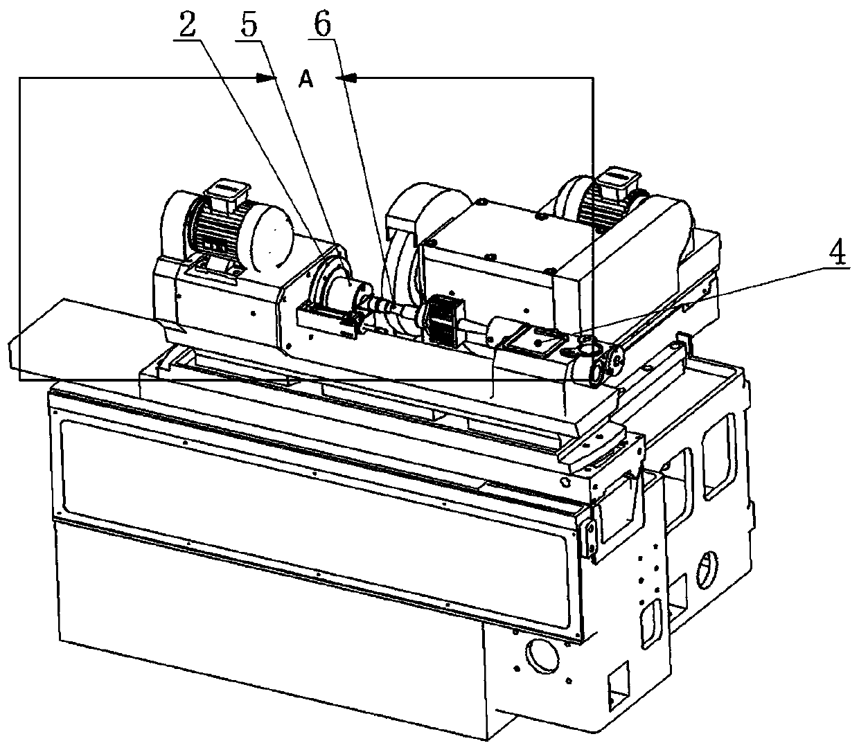
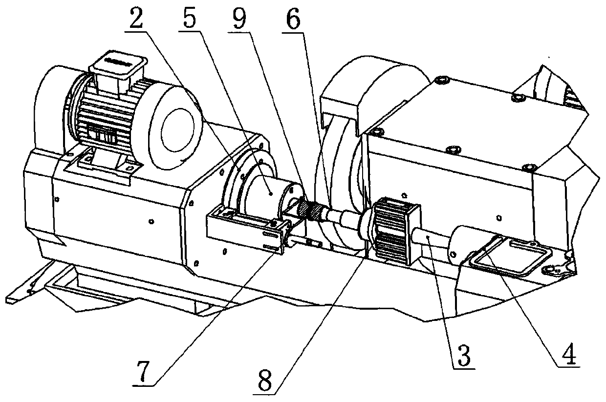
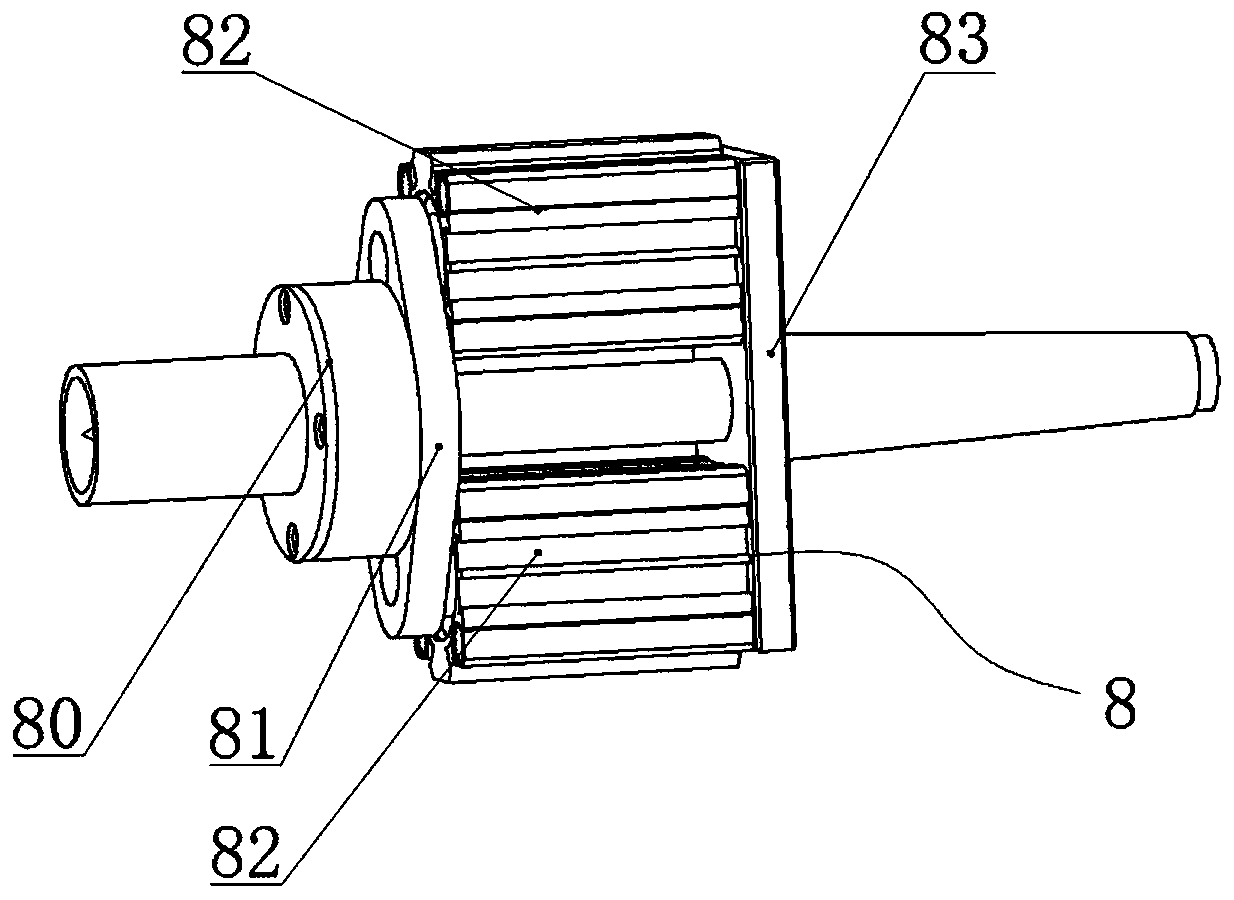
[0024] Such as figure 1 , figure 2 , image 3 , Figure 4 , Figure 5 , Figure 6 , Figure 7 Shown is a special fixture for cylindrical grinding machines. The cylindrical grinding machine includes a first thimble 1, a tail thimble 3, a turntable frame 2 for fixing the first thimble 1, a tailstock frame 4 for fixing the tail thimble 3, and a tailstock frame 4 It can move towards the direction of the turntable frame 2 along the lateral moving platform of the cylindrical grinder, so that the parts to be processed between the first thimble 1 and the tail thimble 3 are tightened between the two. Its special fixture for cylindrical grinding machines includes a chuck sleeve 5, a suspension shaft 6 for hanging and ins...


PUM


Abstract

The invention relates to the field of machining by a grinding machine, in particular to a special fixture for a cylindrical grinding machine. The special fixture is used for abrasive machining of shaft sleeve type parts, the cylindrical grinding machine comprises a head thimble, a tail thimble, a turntable rack for fixing the head thimble and a tailstock rack for fixing the tail thimble, the special fixture for the cylindrical grinding machine comprises a chuck sleeve, a suspension shaft for the shaft sleeve parts, an ejecting mechanism and a pressing mechanism, the chuck sleeve covers the head thimble and is fixed to the turntable rack, one end of the suspension shaft extends into the chuck sleeve, the head thimble is propped against the head end of the suspension shaft, the ejecting mechanism is parallel to the chuck sleeve and the suspension shaft and fixedly connected on the cylindrical grinding machine, and the pressing mechanism is arranged on the tailstock rack in a sleeving manner and used for pressing the shaft sleeve type parts arranged on the suspension shaft in a sleeving manner. According to the special fixture, automatic pressing and automatic dismounting of the partsare realized, coaxiality of the parts during machining is guaranteed, the eccentric condition of the shaft sleeve parts is prevented, and the machining precision of the parts is improved.

Description

technical field [0001] The invention relates to the field of grinding machine processing, in particular to a special fixture for cylindrical grinding machines for grinding shaft sleeve parts. Background technique [0002] With the rapid development of the economy, cylindrical grinding machine fixtures are widely used on machine tools in the industrial field, but there are also many defects in production applications. The processing error is large, which affects the quality of the product; for the processing of sleeve parts with different shapes, different radial dimensions or different axial dimensions, in order to realize the clamping of the workpiece, it is often necessary to replace the fixture device, which virtually increases the fixture design. Manufacturing cost and production preparation cycle, increase production cost. Or some grinding machine fixtures, when clamping or unloading, the loading and unloading time of the workpiece is longer, and the consistency betwee...

Claims


Application Information

Patent Timeline
IPC IPC(8): B24B5/04B24B5/35B24B41/06
CPCB24B5/04B24B5/35B24B5/355B24B41/062
Inventor 赵雷张华杨川陈华余衡匡青云刘祥熙胡琴陈玉芬梁耀辉涂家豪张志毅谷燚
Owner 重庆机电职业技术大学
Learn More