Method for adding a security code to multiple receivers during power-up

a technology for security codes and receivers, applied in transmission systems, non-electrical signal transmission systems, instruments, etc., can solve the problem that the remote control device in the second subset will remain unpaired with the remote controller, and achieve the effect of promoting security

Inactive Publication Date: 2018-09-04
FORMA LIGHTING HK
View PDF15 Cites 4 Cited by
  • Summary
  • Abstract
  • Description
  • Claims
  • Application Information

AI Technical Summary

Benefits of technology

[0017]In one aspect, the invention permits an owner to program a code to control remotely-controlled devices by cycling power. This particular method promotes security. For example, when implemented in a semi-public area such as a store, it makes it difficult for a vandal to use his own remote-controller to essentially hijack control over the remotely-controlled devices since the vandal would both not have the code and also not have access to the power switch.
[0018]The methods and systems described herein also permit light-fixtures throughout an entire store or an area within a store to be easily programmed to respond to their own button codes. This allows two adjacent stores, or regions of a store, to adjust light-fixtures without interfering with each other. Moreover, if one changes the code on the transmitter, or one has forgotten it, it is a simple matter to pair the light-fixtures to the transmitter all over again with a new code.
[0020]The use of a targeted visual-signal makes it easier pair light-fixtures within a particular area. In this embodiment, on can power cycle the light-fixtures, after which one can activate selected light-fixtures using the targeted visual-signal. This will cause only the remotely-controlled devices activated by the targeted visual-signal to respond to that transmitter. Without the use of a targeted-visual signal, such as a laser, light-fixtures that are on the same electrical circuit would have to be disconnected during the pairing process.

Problems solved by technology

However, as a result of having been prevented from exercising their ability to be paired, any remotely-controlled device in the second subset will remain unpaired with the remote-controller.

Method used


Image

  • Method for adding a security code to multiple receivers during power-up
  • Method for adding a security code to multiple receivers during power-up
  • Method for adding a security code to multiple receivers during power-up

Examples


Embodiment Construction

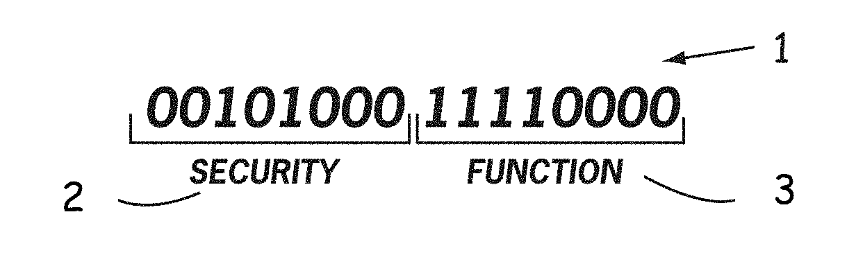
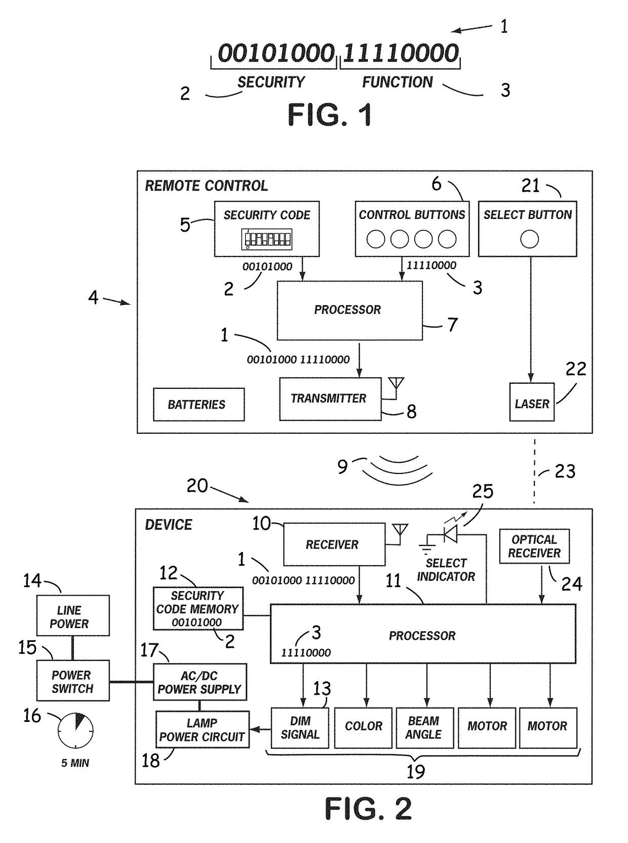
[0057]As shown in FIG. 1, a typical button code for a radio or infrared remote-controller includes bit sequence 1. The number of bits in the bit sequence 1 varies according to implementation. In some embodiments, there are as many as many as twenty-nine bits. The bit sequence 1 include a security code 2 for remotely-controlled devices, such as remote locks, garage door openers, or light-fixtures, and a permanent set of function-control codes 3.

[0058]FIG. 2 shows a remote-controller 4 and a light-fixture 20 to be controlled. The remote-controller 4 has a transmitter 8 and the light-fixture 20 has a receiver 10.

[0059]In operation, the transmitter 8 converts the bit sequence 1 into a modulated signal. It then sends that signal over a wireless link using a suitable carrier wave 9. In some embodiments, the carrier wave 9 is a radio wave, whereas in others, it is infrared light. In either case, the receiver 10 then demodulates the signal and recovers the bit sequence 1.

[0060]The user sets...


PUM


Abstract

A method for configuring a first remotely-controlled device from a plurality of remotely-controlled devices to execute a function in response to a signal from a remote-controller by executing a set of steps at the first remotely-controlled device, wherein said set of steps comprises power cycling said first remotely-controlled device, said power cycling initiating a pairing period, during said pairing period, receiving, from said remote-controller, a first signal, wherein said first signal includes a first security code, and storing said first security code, said method further comprising, after said pairing period, receiving a second signal, said second signal carrying a second security code, comparing said second security code with said first security code, and, in response to said comparison, selecting an action selected from the group consisting of ignoring said second signal and carrying out said function in response to said second signal.

Description

CROSS REFERENCE TO RELATED APPLICATION[0001]This application claims the benefit of the Nov. 20, 2015 priority date of U.S. Provisional Application No. 62 / 257,910, the contents of which are herein incorporated by reference in their entirety.FIELD OF INVENTION[0002]This invention relates to controlling light-fixtures, and in particular, to using a single remote-controller for controlling multiple identical light-fixtures.BACKGROUND[0003]Most simple unidirectional remote-controlled systems using infrared or radio include one remote-controller that is paired with one remotely-controlled device. In some instances, there may be two or more identical remotely-controlled devices within range of that remote-controller's transmitter. In such cases, it may be necessary to prevent that transmitter from controlling a second device within its transmission range. This is a common problem in, for example, a house having multiple remote-controlled ceiling fans.[0004]One solution to this problem incl...

Claims


Application Information

Patent Timeline
Patent Type & Authority Patents(United States)
IPC IPC(8): G08C17/02G08C23/04
CPCG08C17/02G08C23/04G08C2201/20
Inventor DEVLIN, THOMAS E.
Owner FORMA LIGHTING HK
Why Eureka
Try Eureka