Electronic vaporiser system

a technology of electronic vaporizer and electronic vaporizer, which is applied in the direction of program control, special dispensing means, packaged goods, etc., can solve the problems of complex user interaction, simple and attractive rituals, and the complex design of conventional re-fillable e-cigarettes

Active Publication Date: 2018-09-25
AYR LTD
View PDF188 Cites 40 Cited by
  • Summary
  • Abstract
  • Description
  • Claims
  • Application Information

AI Technical Summary

Problems solved by technology

Conventional designs of re-fillable e-cigarette are somewhat complex because re-filling with e-liquid generally requires the user to unscrew the e-cigarette and to then manually drip onto an atomizing coil a small quantity of e-liquid.
The overall user interaction with conventional re-fillable e-cigarettes (covering all aspects of how the user controls, re-fills, re-charges and generally interacts with the device) can therefore be complex and this is reflected in their design, which is often rather technical, with various control buttons.
The complex user interaction that characterizes conventional refillable e-cigarettes has none of the simplicity or attractive ritual of opening a packet of cigarettes and lighting up.

Method used


Image

  • Electronic vaporiser system
  • Electronic vaporiser system
  • Electronic vaporiser system

Examples


case feature 1

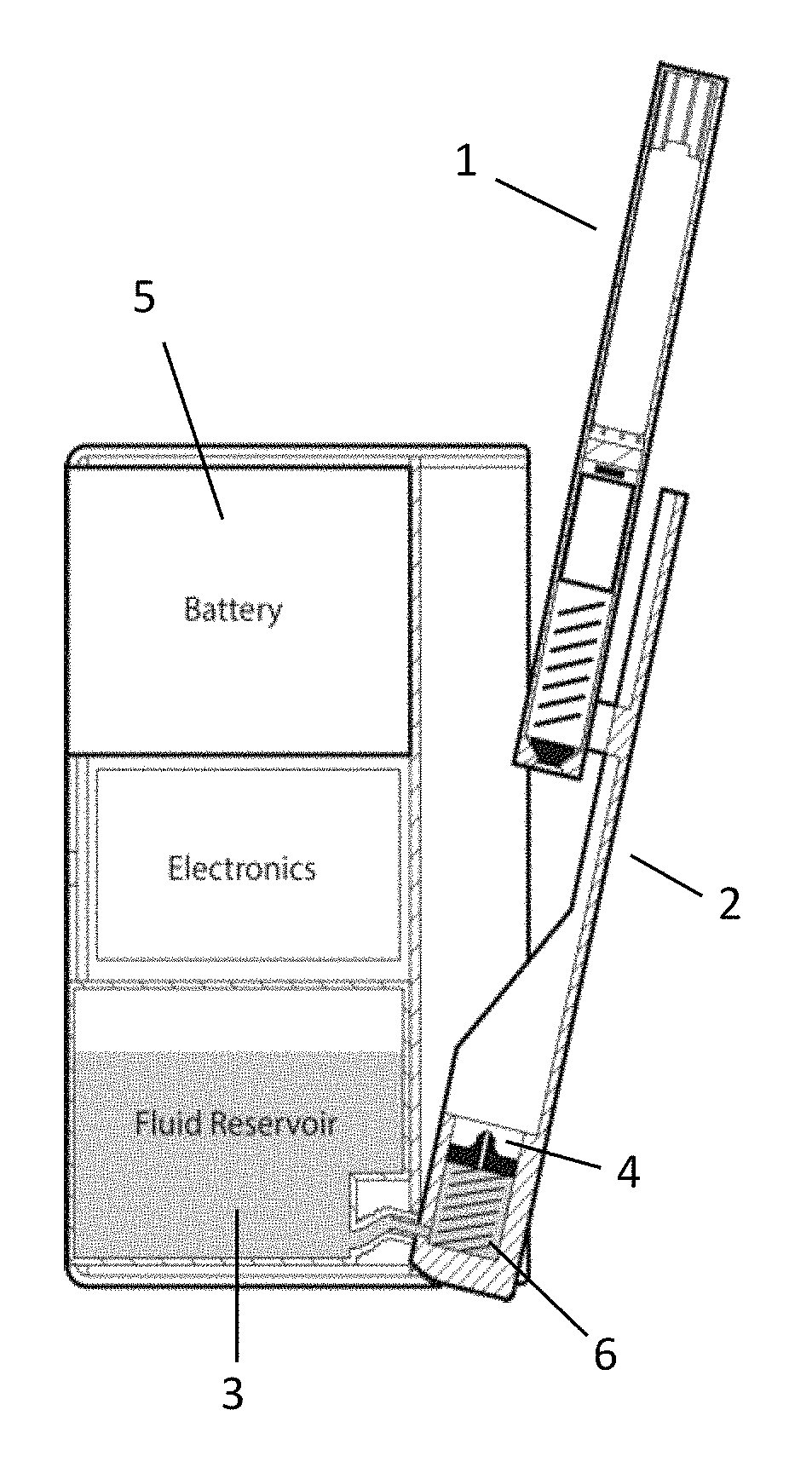
[0118]Key features of the case are the following:[0119] The case includes a piezo-electric pump. The case includes a piezo-electric pump to transfer small but accurate quantities of e-liquid in from the cartridge or other parent reservoir to a child reservoir in the PV.[0120]Case Feature 2: The case or PV has a ‘discrete’ mode. In ‘discrete’ mode, the PV reduces the amount of vapour produced, or its density (e.g. by reducing the coil temperature by 10%) but maintains that temperature within a range where the vaping experience is still good, but vapour quantity or density is reduced. This is useful for a restaurant or office.[0121]Case Feature 3: The case or PV includes a ‘power mode’ with coil temperature monitoring—e.g. to increase the amount of vapour produced, the user can activate a button or sensor on the PV, but crucially coil temperature is measured or inferred or limited to ensure that it remains at a safe operating temperature.[0122]Case Feature 4: The case has a PV ejectio...

case features 1-5

[0237

[0238]Case Feature 1:

[0239]The case includes a piezo-electric pump: the case (or the PV or the cartridge) includes a piezo-electric pump to transfer small but accurate quantities of e-liquid in from the cartridge or parent reservoir to a child reservoir in the PV. This enables mixing from multiple cartridges too. The piezo-electric pump can be used as the fluid transfer mechanism to transfer e-liquid from the cartridge or parent reservoir into the child reservoir in the PV. It can also be used in reverse to suck back out any residual e-liquid in the PV.

[0240]Because the amounts delivered can be accurately metered, this means that the PV (or case or cartridge or an associated application running on a smartphone) can accurately determine the total consumption of e-liquid and / or the amount of e-liquid remaining in a cartridge and also in the PV itself. This in turn can be used in the automatic re-ordering function—for example, when the system knows that the cartridge is down to it...

case feature 2

[0300]

[0301]Case or PV has a ‘discrete’ mode: PV includes a ‘discrete mode’—e.g. to reduce the amount of vapour produced, the user can activate a button or sensor on the PV (or case, or connected app) and that alters the operation of the operation of the atomising device in such a way as to decrease the vapour produced—for example, it could reduce the power used, or increase the VG proportion compared to PG, if that is possible—e.g. the case or PV can mix differing proportions of PG and VG, or alter the frequency or other operational parameters (e.g. duty cycle) of a piezo-electric, thermal bubble jet or ultrasonic atomiser. Consequently, the density or thickness of the vapour produced by the PV can be significantly reduced; this is particularly useful indoors, when the user might wish to vape very discretely. The strength of the ‘hit’ can also be decreased too, because the amount of nicotine inhaled will be reduced; this can be useful where the user wishes to reduce their nicotine ...


PUM

PropertyMeasurementUnit
volumeaaaaaaaaaa
lengthaaaaaaaaaa
lengthaaaaaaaaaa

Abstract

An electronic cigarette vaporizer system includes a case and a vaporizer that is stored in the case; the system includes a non-contact sensor that detects release or withdrawal of the vaporizer from the case. When withdrawal of the vaporizer is detected, then the vaporizer electronic circuitry changes state, e.g. to a ready mode, or a pre-heating mode in which an inhalation detector is activated or to a heating mode, where an atomizing unit in the vaporizer is at least partly activated so that the vaporizer is fully heated when the first inhalation is taken.

Description

CROSS-REFERENCE TO RELATED APPLICATIONS[0001]This application is a continuation-in-part of U.S. application Ser. No. 14 / 842,067, filed Sep. 1, 2015, which is a continuation-in-part of U.S. application Ser. No. 14 / 633,887, filed Feb. 27, 2015, which is based on and claims priority to UK Application No. 1403566.1, filed Feb. 28, 2014; UK Application No. 1408173.1, filed May 8, 2014; UK Application No. 1413018.1, filed Jul. 23, 2014; UK Application No. 1413019.9, filed Jul. 23, 2014; UK Application No. 1413021.5, filed Jul. 23, 2014; UK Application No. 1413025.6, filed Jul. 23, 2014; UK Application No. 1413027.2, filed Jul. 23, 2014; UK Application No. 1413028.0, filed Jul. 23, 2014; UK Application No. 1413030.6, filed Jul. 23, 2014; UK Application No. 1413032.0, filed Jul. 23, 2014; UK Application No. 1413034.8, filed Jul. 23, 2014; UK Application No. 1413036.3, filed Jul. 23, 2014; UK Application No. 1413037.1, filed Jul. 23, 2014; U.S. Provisional Application No. 62 / 045,651, filed S...

Claims


Application Information

Patent Timeline
Patent Type & Authority Patents(United States)
IPC IPC(8): A24F47/00A24B15/16B67D7/02H04M1/725B67D7/36G01K13/02B67D7/78F16K25/00F16K24/04B67D7/62H05B3/14B65D85/00B67D7/42A61M11/04A61M15/06B67D7/14B67D7/34G05B19/416G06F21/44H02J7/00H05B1/02A24F15/14A24F15/18B65D83/00B67D7/54F04B43/04F04B49/06G01R31/28G06Q30/00B65B3/04A24F15/015A24F40/10A24F40/51A24F40/95H04M1/72412H04M1/7243
CPCB67D7/36A24F15/14A24F15/18A24F47/008A61M11/042A61M15/06B65D83/0038B65D85/70B67D7/02B67D7/0288B67D7/145B67D7/346B67D7/42B67D7/54B67D7/62B67D7/78F04B43/046F04B49/06F16K24/04F16K25/005G01K13/02G01R31/2825G05B19/4166G06F21/44H02J7/0042H02J7/0044H02J7/0052H02J7/0054H04M1/7253H04M1/72547H05B1/0244H05B3/141A24B15/167H05B2203/021A61M2205/3331A61M2205/3368A61M2205/3584A61M2205/50A61M2205/583A61M2205/60A61M2205/8206B65B3/04G05B2219/37371G06Q30/016H02J7/0063F16K15/044F16K24/00H05B1/0227A61M2205/13A61M2205/14A61M2205/27A61M2205/3379A61M2205/3553A61M2205/3561A61M2205/3569A61M2205/3592A61M2205/8237A61M2209/045A61M2209/086F04B17/003F04B19/006F04B35/04F04B45/047F04B2203/0404H02J7/342Y02A30/00A24F15/015A24F40/10A24F40/95A24F40/51H04M1/72412H02J7/00H04M1/7243
Inventor MURISON, IANMARSH, STEPHEN
Owner AYR LTD
Why Eureka
Try Eureka