Tool bit of ultrasonic osteotome and ultrasonic osteotome including the same

a technology of ultrasonic osteotome and tool bit, applied in the field of medical equipment, can solve the problems of large risk, low cutting speed, and the majority of the tip not being an effective main cutting part, so as to improve the chance of surgery success, reduce the time required for surgery, and increase the cutting speed

Active Publication Date: 2018-10-02
CAO +1
View PDF28 Cites 2 Cited by
  • Summary
  • Abstract
  • Description
  • Claims
  • Application Information

AI Technical Summary

Benefits of technology

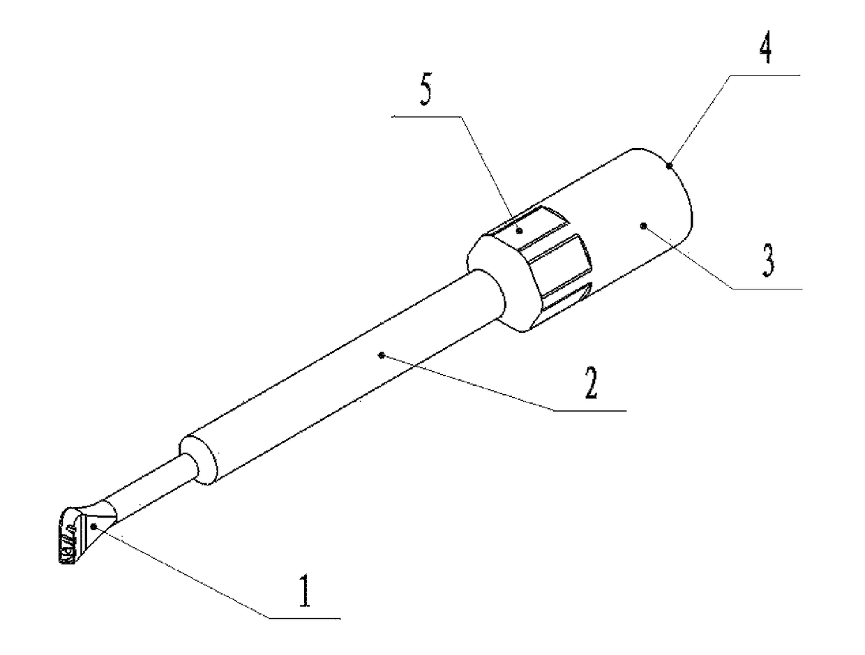
[0008]In order to solve at least one of the above problems in the prior art, the present disclosure provides a tool bit of an ultrasonic osteotome that has a high efficiency and a high cutting speed to reduce the time required for surgery.
[0009]Further, the present disclosure provides a tool bit of an ultrasonic osteotome that may be positioned correctly in cutting operation to improve the chance of success in surgery.
[0012]The tool bit according to an embodiment of the present invention, may increase the cutting speed to reduce the time required for surgery, and may be positioned correctly in cutting operation without skidding to improve the chance of success in surgery.
[0028]Such design of the ultrasonic osteotome according to the embodiment of the present invention, not only may increase the cutting speed to reduce the time required for surgery, but also may be positioned correctly in cutting operation without skidding to improve the chance of success in surgery.

Problems solved by technology

Conventional orthopedic equipments such as an electric drill and ultrasonic osteotome apply downward forces in most of operations in surgery, which may bring great risk.
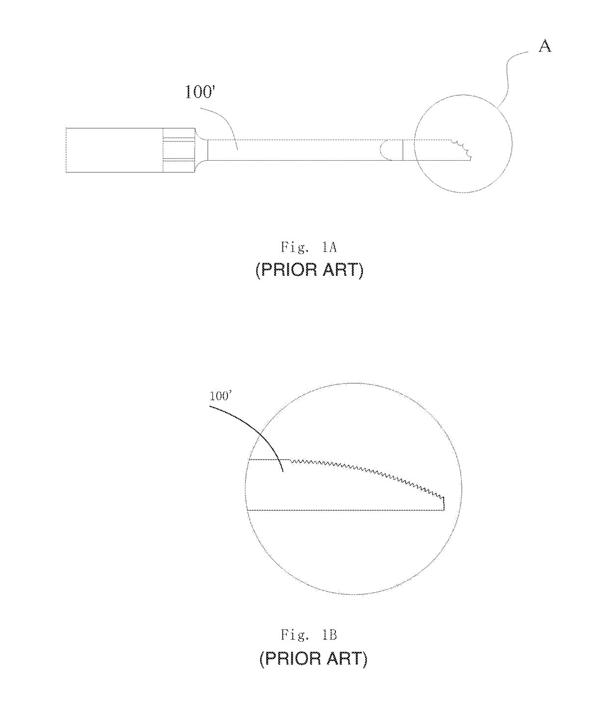
However, a majority part of the tip does not constitute an effective main cutting part, as shown in FIG. 1B.
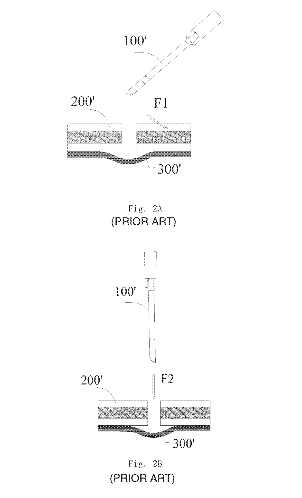
When the cutting operation is desired, the tool bit 100′ needs to apply the force downwardly to the osseous tissue, which may not only cause a low cutting speed and a low efficiency, but also cause the tool bit with a plurality of teeth to break in operation, as indicated by F2 in FIG. 2B.
As the force is applied downwardly in operation, it tends to destroy the tissues which are located below the cutting location and are undesired to be injured.
In this way, the risk of surgery may be increased significantly, chance of success in surgery may be reduced, and operation difficulty of a doctor may be increased.
If the spinal cord is injured, the patient will at least lose a function, be permanently paralysed, even decease.

Method used


Image

  • Tool bit of ultrasonic osteotome and ultrasonic osteotome including the same
  • Tool bit of ultrasonic osteotome and ultrasonic osteotome including the same
  • Tool bit of ultrasonic osteotome and ultrasonic osteotome including the same

Examples


Embodiment Construction

[0040]The specific embodiments of the present invention will be described in detail below with reference to accompanied figures. Throughout the description, identical or similar reference numerals represent identical or similar members. It should be noted that embodiments described herein are depicted only for illustration, instead of limiting to the present invention.

[0041]In the description of the present disclosure, it should be noted that the orientations or positions represented by the terms of “up”, “down”, “vertical”, “horizontal”, “top”, “bottom”, “inner” and “outer” and the like are based on the figures. It is given only by way of examples, instead of being intended to limit the device or element to have a special orientation or to be configured and operated in a special orientation. Thus, it cannot be understood as limiting of the present invention. In addition, the terms of “first” and “second” are depicted only by illustration, instead of being intended to define which o...


PUM


Abstract

A tool bit (100) of an ultrasonic osteotome includes: an arbor (2); and an end portion (1) of the tool bit connected to a front end of the arbor (2). The end portion (1) of the tool bit has a spoon-like shape and has a toothed front edge. An ultrasonic osteotome including the tool bit is also provided.

Description

CROSS REFERENCE TO RELATED APPLICATIONS[0001]This is a Continuation application of International Application Serial No. PCT / CN2014 / 079578 filed on Jun. 10, 2014, which claims the benefit of Chinese Application No. 201320435087.6 filed on Jul. 22, 2013, the disclosures of which are hereby incorporated by reference.BACKGROUND[0002]1. Field of the Invention[0003]The present disclosure relates to a technical field of medical equipment, in particular to an improved tool bit of ultrasonic osteotome and an ultrasonic osteotome comprising the tool bit.[0004]2. Description of the Related Art[0005]Conventional orthopedic equipments such as an electric drill and ultrasonic osteotome apply downward forces in most of operations in surgery, which may bring great risk.[0006]FIG. 1A shows a typical structure of a conventional tool bit 100′ of ultrasonic osteotome, which has a plurality of teeth and a wide tip. However, a majority part of the tip does not constitute an effective main cutting part, a...

Claims


Application Information

Patent Timeline
Patent Type & Authority Patents(United States)
IPC IPC(8): A61B17/32A61B17/3209A61B17/3205A61B17/16
CPCA61B17/320068A61B17/1604A61B17/1659A61B17/32A61B17/3205A61B17/3209A61B2217/007A61B2017/32007A61B2017/320072A61B2017/320074A61B2017/320075A61B2017/320082
Inventor CAOLI, CHUNYUAN
Owner CAO
Why Eureka
Try Eureka