Optical module package

Active Publication Date: 2018-10-02
CLOUD LIGHT TECH LTD
View PDF3 Cites 2 Cited by
  • Summary
  • Abstract
  • Description
  • Claims
  • Application Information

AI Technical Summary

Benefits of technology

[0023]As described above, by the present invention, not only the vibration and shock which reach the fiber unit are decreased by the elastic member in the housing but also the load caused by the temperature-humi

Problems solved by technology

However, the conventional optical module packages, disclosed in each patent document, have following problems because the elastic members are accommodated in the housings.
F

Method used


Image

  • Optical module package
  • Optical module package
  • Optical module package

Examples


Embodiment Construction

[0048]In the following, embodiments of the present invention will be described with reference to the drawings. Note that the same components will be referred to with the same numerals or letters, while omitting their overlapping descriptions.

[0049](Structures of Optical Module Package)

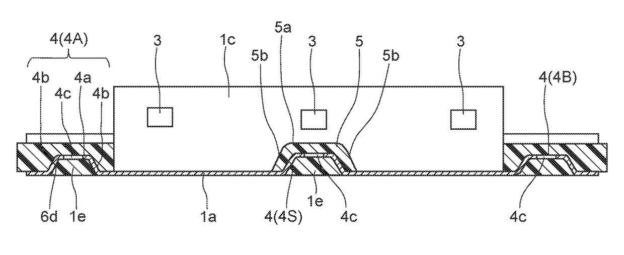
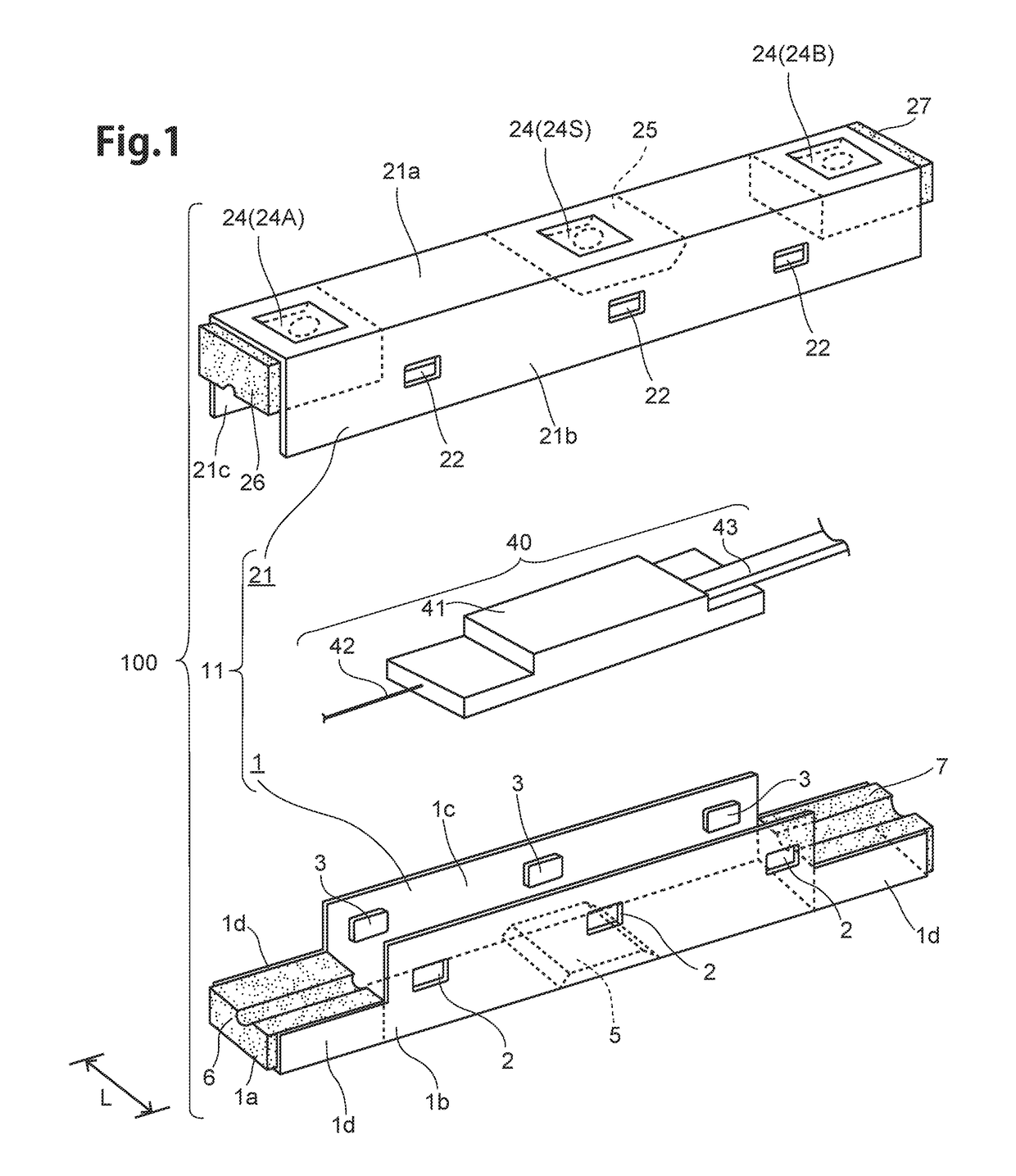
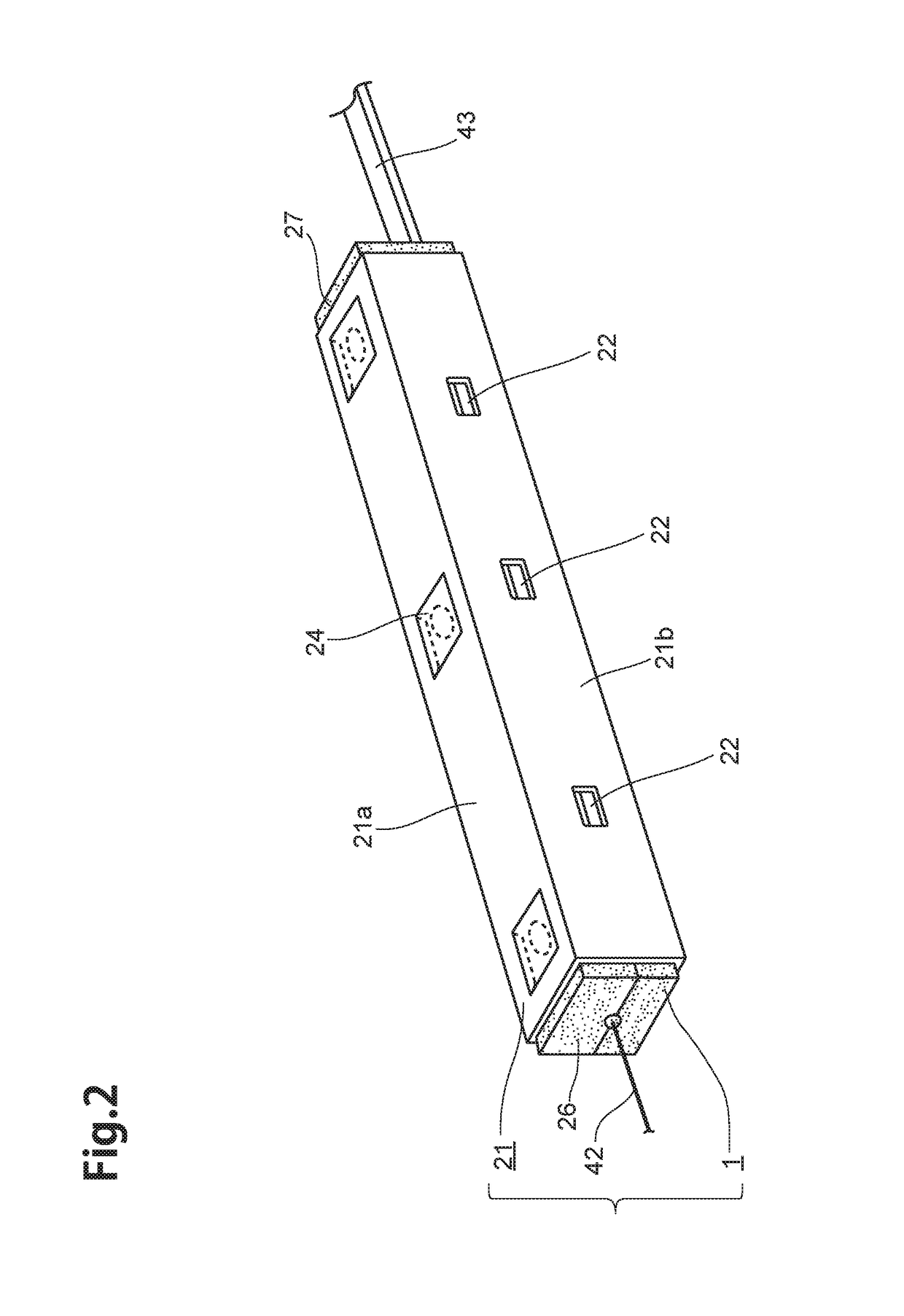
[0050]To begin with, the structure of an optical module package 100 according to the embodiment of the present invention will be explained with reference to FIG. 1 to FIG. 16. Here, FIG. 1 is an exploded perspective view illustrating the optical module package 100 according to the embodiment of the present invention, FIG. 2 is a perspective view illustrating the optical module package 100. FIG. 3 is a plan view illustrating a bottom case 1, FIG. 4 is a right-side elevation view illustrating the bottom case 1. FIG. 5 is a plan view illustrating the bottom case 1 in a state which elastic support part 5, side elastic support parts 6, 7 are removed. FIG. 6 is a sectional view taken along the line 6-6 in FI...


PUM


Abstract

An optical module package has a first case, a second case and a fiber unit. The first case has a case bottom-part formed along the length direction of the fiber unit, a bottom convex-part formed on the case bottom-part so as to project toward inside direction of the first case and an elastic support part made of elastic member and covering the bottom convex-part. The optical waveguide device is supported by the elastic support part and the optical fiber is arranged at the distant position from the elastic support part.

Description

[0001]This application claims priority to CN Utility Model Application No. 201720664417.7 filed Jun. 8, 2017, the entire contents of each of which are hereby incorporated by reference.BACKGROUND[0002]Field of the Invention[0003]The present invention relates to an optical module package in which a fiber unit including an optical waveguide device and an optical fiber connected to each other is accommodated in a housing.[0004]Related Background Art[0005]There is conventionally known optical module packages in which an optical waveguide device, formed with a plurality of branched optical waveguides, is connected with an optical fiber and they are accommodated in a housing.[0006]Conventionally, the optical module packages, which an elastic member and the fiber unit are accommodated in the housing, are known (see for example, JP Patent laid-open Publication 2005-10508 (also referred to as Patent Document 1), JP Patent laid-open Publication H8-286075 (also referred to as Patent Document 2)...

Claims


Application Information

Patent Timeline
IPC IPC(8): G02B6/38G02B6/30G02B6/36
CPCG02B6/30G02B6/3616G02B6/3632G02B2006/1215
Inventor FUKAYA, HIROSHIGOTO, MASANORI
Owner CLOUD LIGHT TECH LTD
Why Eureka
Try Eureka