Vise grip pliers

a technology of pliers and grips, applied in the field of pliers, can solve the problems of increasing manufacturing costs, affecting the quality of pliers, so as to improve the convenience of use, save manufacturing costs, and simplify the structure.

Inactive Publication Date: 2018-10-09
SOHN WON HO
View PDF11 Cites 0 Cited by
  • Summary
  • Abstract
  • Description
  • Claims
  • Application Information

AI Technical Summary

Benefits of technology

[0029]In the present invention, the natural functions of the pliers and vies can be implemented through a simplified and improved structure, which makes it possible to provide an enhanced effect in terms of convenience when in use.
[0030]Moreover, since a simplified configuration which is not much different from the typical pliers, can be maintained, the manufacturing cost can be saved as compared to the conventional vies pliers which have complicated configurations.

Problems solved by technology

For this reason, an interval adjustment may cause inconvenience, and the whole configuration (three hinges, a spring, a support member, an adjusting screw and a shaft) may be complicated and look rough.
The weight thereof may be heavy, and a manufacturing cost may increase.
The aforementioned patent document 1 (the Korean patent laid-open number 10-1999-0080401) have the disadvantages wherein it may provide multiple functions, but an abnormal function may occur due to the abrasion of each hinge pin after a long time use since a plurality of hinge pin connection structures are adapted, and an elastic member is deformed after a long time use since the elastic member (a spring) providing a recovery force and a link rotation function support member are employed, and a manufacturing cost may rise due to the use of an adjusting scree configured to support a side end of the support member and a complicated configuration, and a long time use is not available, and it necessarily needs to adjust an adjusting screw during a clamping operation so as to clamp a predetermined object in response to the thickness of a processed object, which may cause a complicated procedure for each required operation.

Method used


Image

  • Vise grip pliers
  • Vise grip pliers
  • Vise grip pliers

Examples


Embodiment Construction

[0041]The present invention is referred to a combined use of a vise and pliers which can be implemented based on the use of a ring pin.

[0042]The present invention will be described with reference to the accompanying drawings.

[0043]Throughout the description of the present invention, the configuration and sizes of the components illustrated in the drawings may be simplified unless such simplifications are inferred with the descriptions of the present invention.

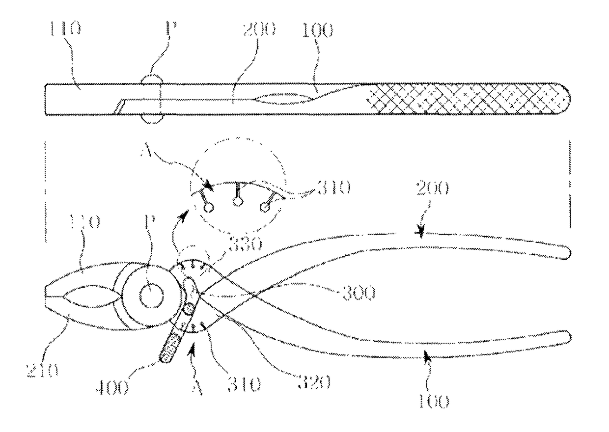
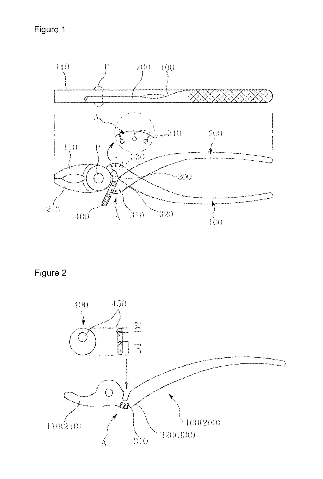
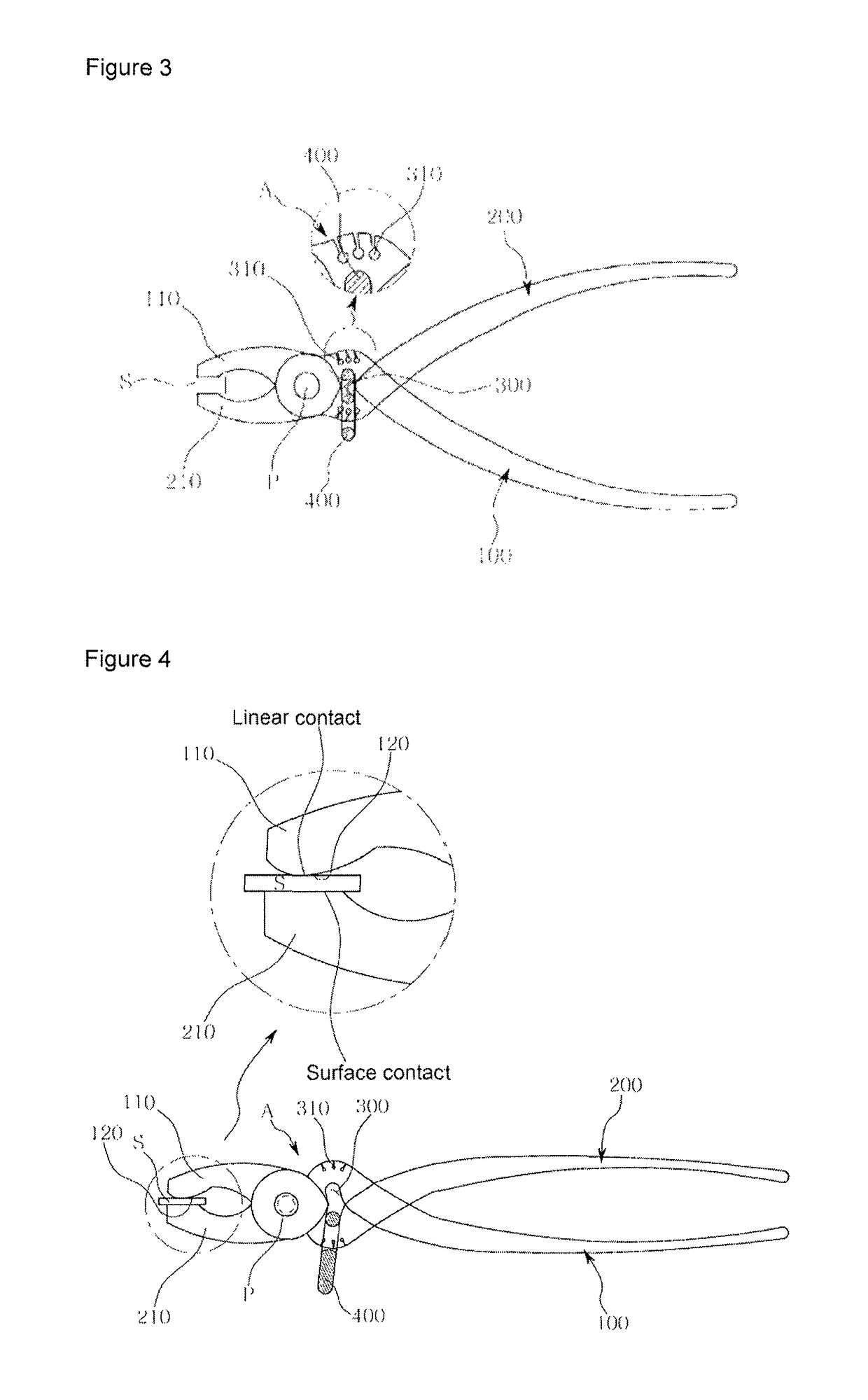
[0044]As illustrated in FIG. 1, the vise grip pliers according to the present invention may be configured in such a way that the pliers cross each other in a first X-shape as they are axially engaged through a hinge pin (P) through an axial hole formed at a body 330 of a first handle 100 at a front end of which a first haw 110 is provided and a body 320 of a second handle 200 wherein a second jaw 210 is provided, and then a ring pin hole 300 may be formed by means of a first bent part (A) wherein a second X-shaped cross is form...


PUM


Abstract

Vise grip pliers capable of stably clamping an object with a simpler structure than that of normal vise pliers and also providing a vise grip function by means of a simple operation. To this end, the present invention has first and second jaws formed at the front end of a body, forms a space in which a ring pin can be provided, by outwardly bending handles, and then rebending the same without extending the handles immediately after hinge parts cross each other, in addition to, one hinge crossing the jaws in an X-shape by a hinge pin (P), and ensures the vise grip function by providing a tapered ring in the ring pin space, and then recrossing the handles in an X shape.

Description

TECHNICAL FIELD[0001]The present invention relates to vise grip pliers which are configured in a simplified structure and are able to stably and surely bite, for example, a flat, angular or rounded object, while carrying out a vise grip function through a simplified operation.BACKGROUND ART[0002]Typical pliers are configured in an X-shape, wherein upper and lower bodies are assembled though a hinge pin, and when a user grips both handles with a predetermined griping strength, the front jaws bite an object. The user needs to keep gripping the handles in order for the object to be held bitten for a predetermined time.[0003]Meanwhile, the vise pliers are being called, for example, a vise grip, vise grip pliers, etc. and are able to keep biting the object for a long time.[0004]The vise grip pliers use an adjusting screw installed at a first or second handle so as to adjust the interval between the first and second jaws which are configured to bite a processed object. For this reason, an...

Claims


Application Information

Patent Timeline
Patent Type & Authority Patents(United States)
IPC IPC(8): B25B7/12B25B7/14B25B7/08B25G1/10
CPCB25B7/12B25G1/10B25B7/14B25B7/08
Inventor SOHN, WON HO
Owner SOHN WON HO
Why Eureka
Try Eureka