Connection arrangement of two bodies with a removable clamp

Active Publication Date: 2018-10-09
METAL WORK
View PDF17 Cites 0 Cited by
  • Summary
  • Abstract
  • Description
  • Claims
  • Application Information

AI Technical Summary

Benefits of technology

[0060]Yet a further purpose of the present invention is that of proposing a connection arrangement of at least two bodies of components of a move

Problems solved by technology

The design and the manufacturing of every single connection arrangement that is “customised” as a function of the machine tool and of the mechanical automation group to be made are particularly burdensome both in terms of time, and in terms of costs and limit the possibilities of modifications and variants.
This, consequently, involves a complication and a series of burdens, in terms of time and costs, for the design, manufacturing, provision and management at the store of the different types of “adapters”.
Moreover, regardless of how wide the range of foreseen “adaptors” may be, the connection types that can be made are in any case limited and do not satisfy all possible situations.
However, such a connection system of the known type also has some application limitations.
However, even such a known connection system has some drawbacks.
A first drawback is represented by the fact that the two components that are connected to one another are spaced from one another by a distance that is greater than the diameter of the threaded stems and that is equal to the thickness of the “inserts” arranged between th

Method used


Image

  • Connection arrangement of two bodies with a removable clamp
  • Connection arrangement of two bodies with a removable clamp
  • Connection arrangement of two bodies with a removable clamp

Examples


Embodiment Construction

[0076]It is worth underlining that in the present description we shall use adjectives such as “first” and “second” purely to make the description clearer.

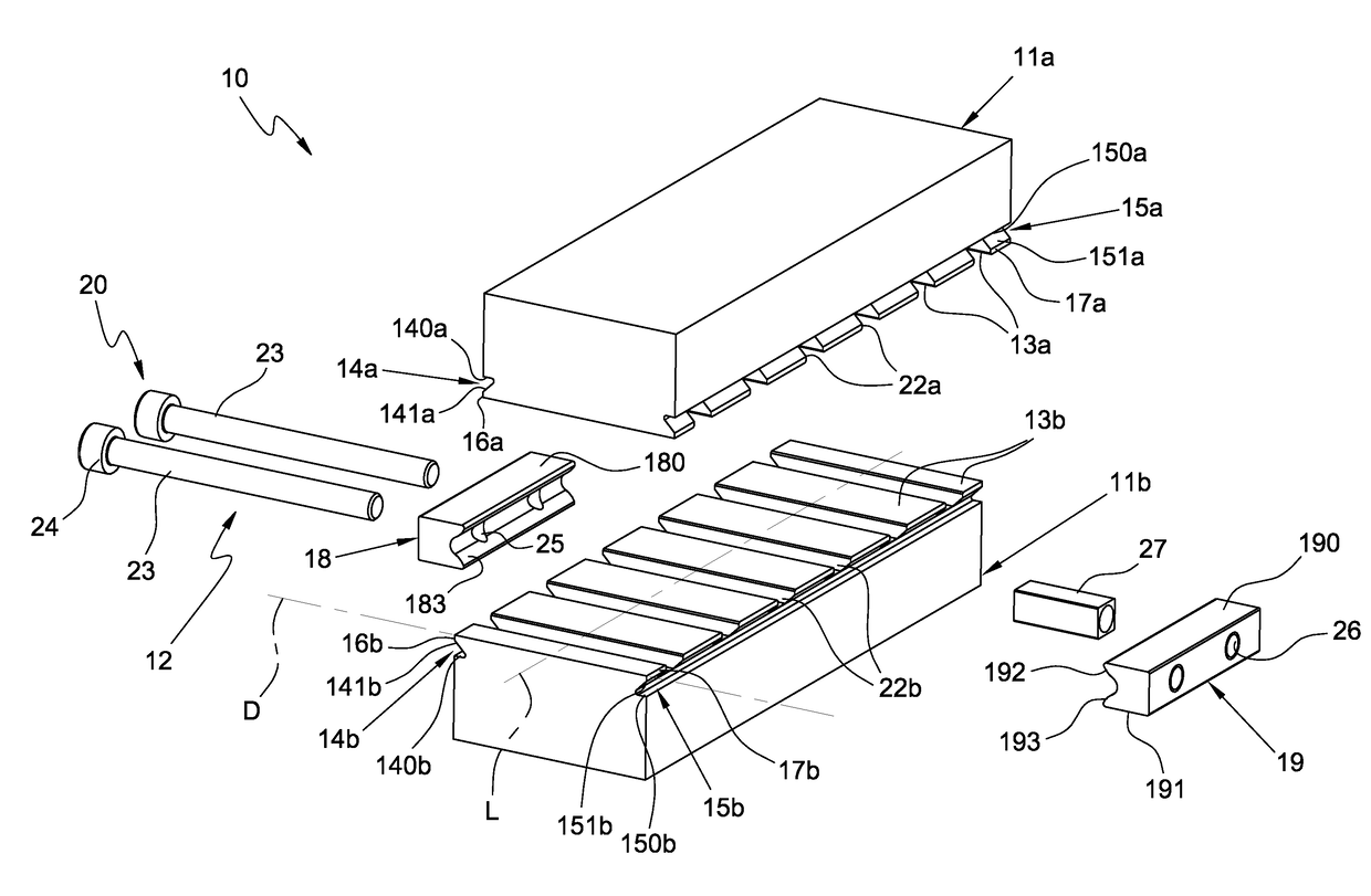
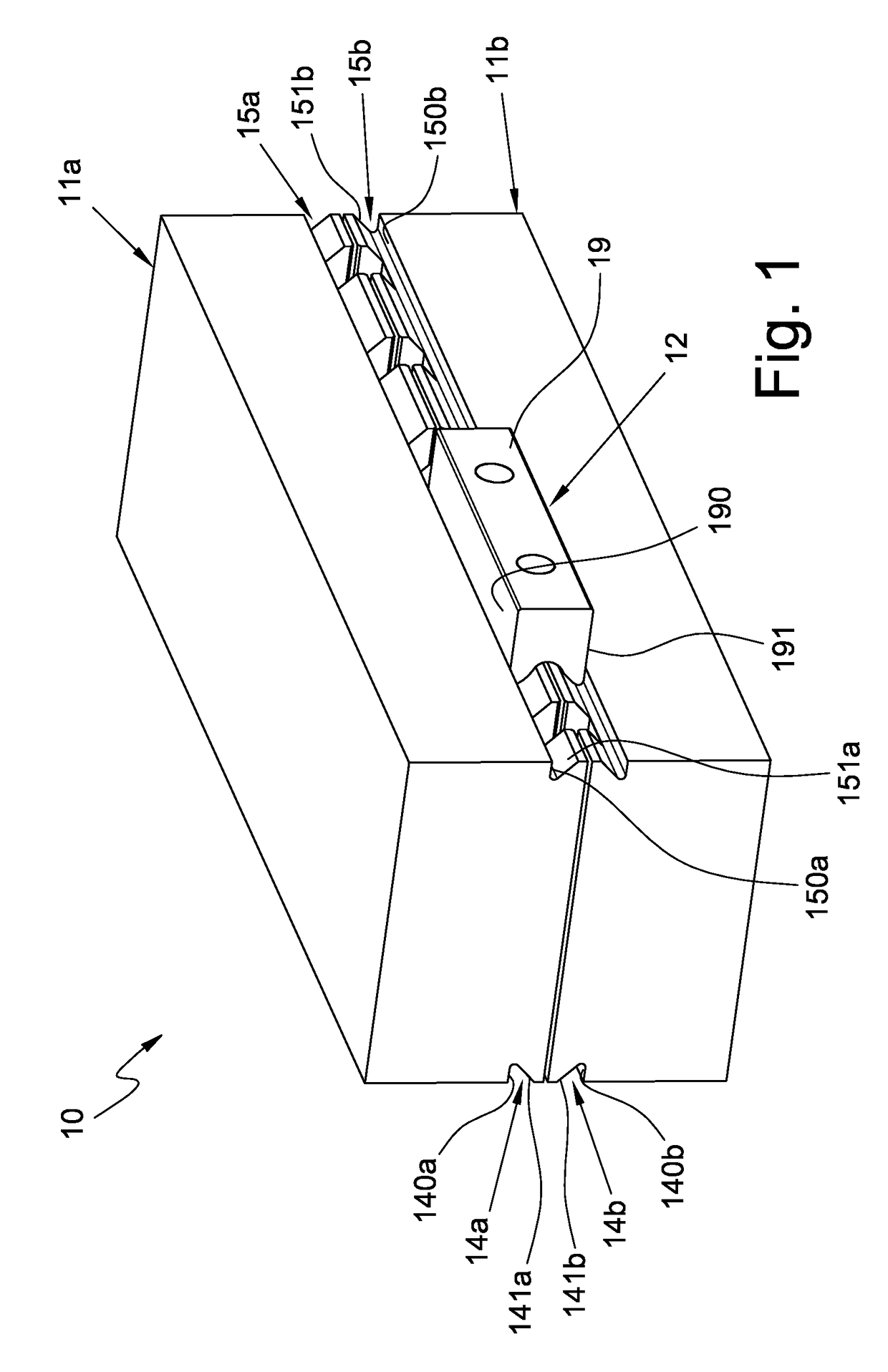
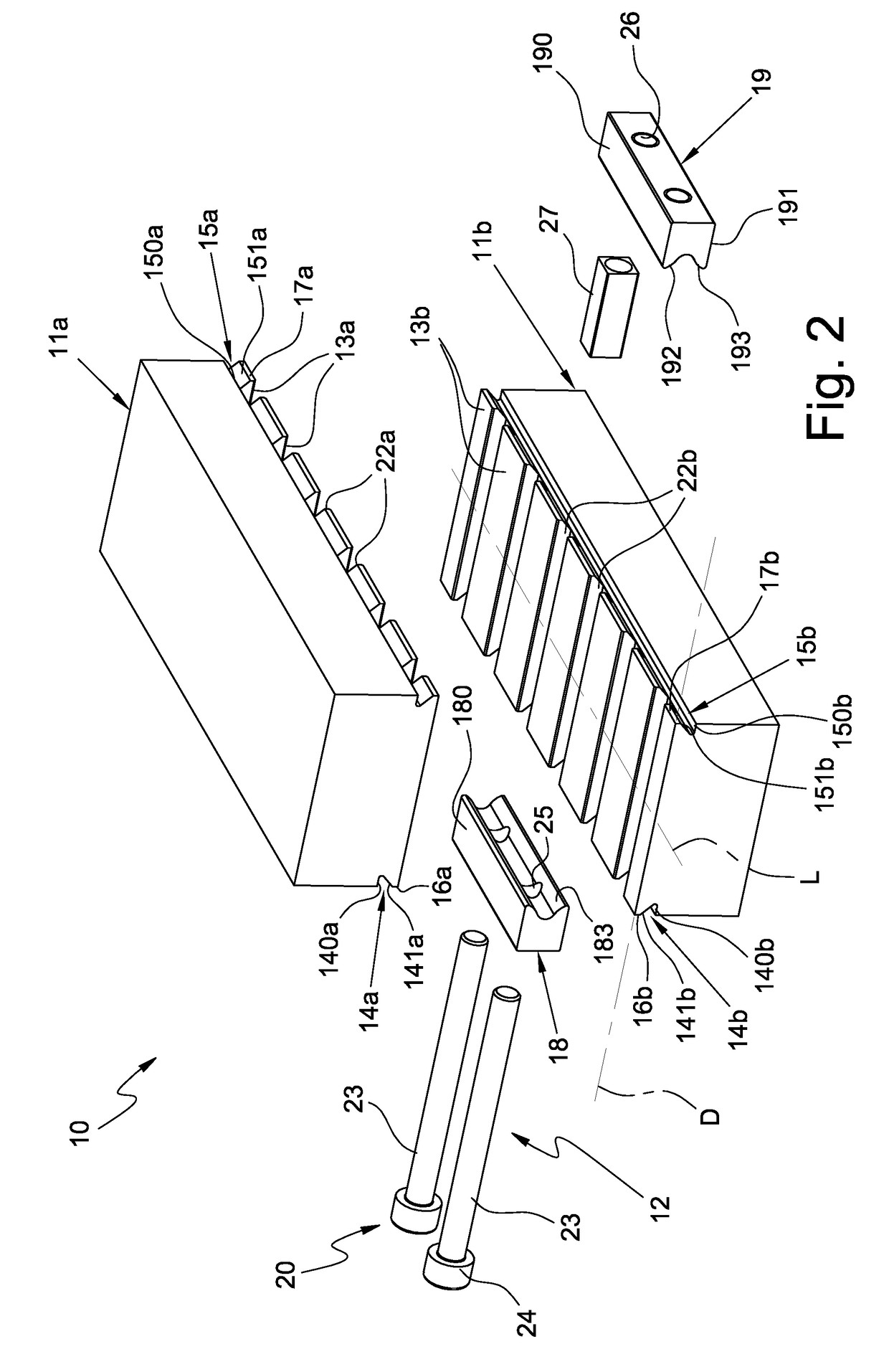
[0077]With reference to the attached figures reference numeral 10 wholly indicates a connection arrangement comprising at least two bodies 11a and 11b to be connected to each other and a constraining group 12 for removably constraining such two bodies 11a and 11b to each other.

[0078]The two bodies 11a and 11b are the bodies of components of a movement mechanical automation group, in particular of components for transmitting, transforming and driving linear, rotary movements or combinations thereof, except for the components of the power circuit that supplies the mechanical automation group.

[0079]The two bodies 11a and 11b, for example, can be the bodies of linear or rotary actuators of the pneumatic, hydraulic or electric type, clamps, slides, profiles, guide profiles and the like.

[0080]It is worth underlining that in the attached ...


PUM


Abstract

A connection arrangement having at least two bodies of components to be connected to each other and a constraining group for constraining two bodies to each other in a removable manner is disclosed. When the two bodies are in the connection configuration to each other, a recess of one of them defines with a corresponding recess of the other one a respective coupling seat with the constraining group, having at least one pair of locking clamps insertable into a respective coupling seat. When the two bodies are in the connection configuration to each other, they are spaced from each other so that their faces do not have portions in mutual contact with each other.

Description

CROSS-REFERENCE TO RELATED APPLICATIONS[0001]This application is a 371 of PCT / IB2014 / 063087, filed Jul. 14, 2014, which claims the benefit of Italian Patent Application No. MI2013A001256, filed Jul. 26, 2013.FIELD OF THE INVENTION[0002]The present invention refers to a connection arrangement of at least two bodies of components of a movement mechanical automation group with a removable constraining group.BACKGROUND OF THE INVENTION[0003]For the purposes of the present description, by movement mechanical automation group we mean to indicate a group of components for transmitting, transforming and driving linear or rotary movements, which components are connected to one another and are combined so as to be able to actuate a predefined series of movements, except for the components of the power circuit that supplies such a group.[0004]Such components comprise, in particular, pneumatic, hydraulic or electric actuators, slides, clamps, profiles, guide profiles or the like.[0005]Mechanica...

Claims


Application Information

Patent Timeline
IPC IPC(8): F16B2/12F16B5/00
CPCF16B5/0072F16B2/12F16B5/00
Inventor TAMIOZZO, CORRADO
Owner METAL WORK
Why Eureka
Try Eureka