Method for analysis of thermal resistance

a thermal resistance and analysis method technology, applied in the direction of thermal conductivity of materials, instruments, calibrators, etc., can solve the problems of inability to obtain precise thermal resistance, inability to judge heat dissipation characteristics and internal defects accurately, and difficulty in measuring thermal resistance, etc., to achieve wide application scope and high accuracy

Active Publication Date: 2018-10-09
HANGZHOU EVERFINE PHOTO E INFO
View PDF3 Cites 0 Cited by
  • Summary
  • Abstract
  • Description
  • Claims
  • Application Information

AI Technical Summary

Benefits of technology

[0017]The time is from the beginning of the temperature rise / fall to the moment of thermal equilibrium. The temperature change along the time in each moment of this process can be measured. The function relationship is solved according to the temperature change of the heat source to obtain the distribution data of the thermal capacitance and thermal resistance on the heat flow path. As an optimization, in the time segment where the temperature of the heat source changes rapidly, accurate temperature change information of the heat source is obtained by enhancing the measurement frequency of the temperature so as to accurately solve the above function relationship and obtain accurate distribution data of the thermal capacitance and resistance on the heat flow path.
[0051]Given all that, the present invention has the following beneficial effects: by applying the thermal model parameters of each heat conduction component to the analysis of the DUT thermal resistance structure model and the thermal resistance structure function, the analysis error which is caused by the temperature measurement error can be reduced. In addition, the thermal resistance of the DUT interface and the precise inner distribution of each heat conduction components and heat conduction model bidirectionally based on temperature data and thermal model parameters can be obtained. Therefore, realizing the quantitative analysis of the DUT thermal resistance structure provides an important basis for identification of the heat conduction defects inside the DUT. The method can be widely used for thermal resistance analysis of various devices, such as diodes, triodes and other semiconductor devices, and the analysis results can be corrected by using similar standard devices. The method features in simplicity d, high accuracy, high speed, wide application scope, etc.

Problems solved by technology

Because of only basing on temperature data of the DUT, the results of these methods are influenced by temperature measurement accuracy greatly, so for each heat conduction component, the precise thermal resistance can't be obtained and the problems of heat dissipation characteristics and internal defects can't be judged accurately.
However, influenced by the surface characteristic and the connection layer of each heat conduction component during the test and analysis of the thermal resistance structure, for example, the difficulty in confirming the thickness of the contact surface, irregular shape of connection layer and anisotropy of the materials of the heat conduction contact surface, generally, the thermal resistance is difficult to measure.
Thus the effect of heat contact between the components can't be judged accurately and objectively, causing difficulties to the manufacturers and designers to improve the heat dissipation characteristic.

Method used


Image

  • Method for analysis of thermal resistance
  • Method for analysis of thermal resistance
  • Method for analysis of thermal resistance

Examples


embodiment 1

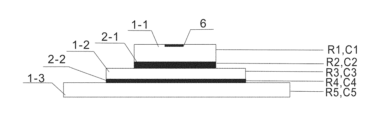
[0067]As shown in FIG. 1, in this embodiment, the DUT is an LED, consisting of a PN junction, a chip (1-1), a first contact interface (2-1) and an aluminum substrate (1-3). As the heat source 6 of LED, the PN junction is located in the chip (1-1). The first contact interface (2-1) and second contact interface (2-2) are connecting layer of different materials and shapes respectively.

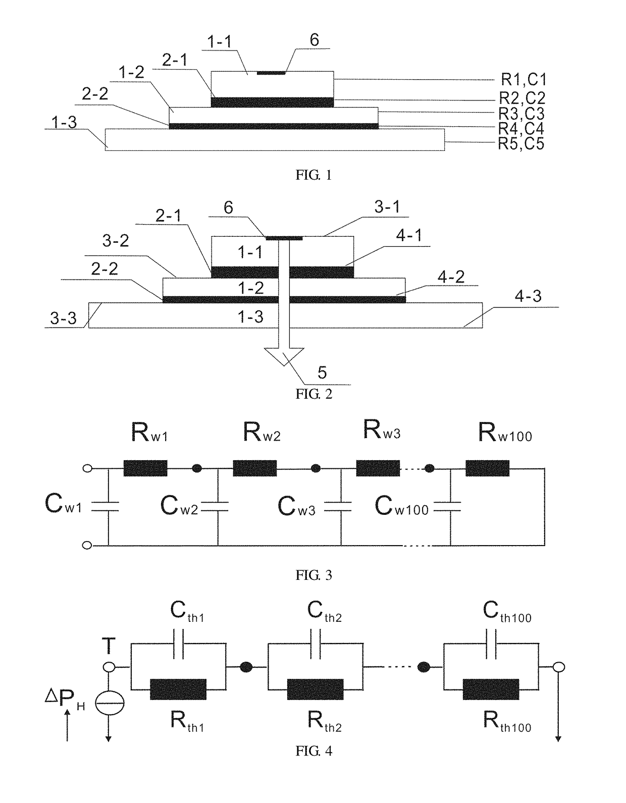
[0068]The heat conduction process of the LED is equivalent to the one-dimensional heat conduction, as shown in FIG. 2. The heat produced by the PN junction on chip (1-1) flows through the chip (1-1), the first contact interface (2-1), metal substrate (1-2), the second contact interface (2-1) and aluminum substrate (1-3) in turn along the one-dimensional heat flow path 5 as shown in the figure. The upper and lower surfaces of the chip (1-1), metal substrate (1-2) and aluminum substrate (1-3) are respective heat conduction interfaces, and the upper surface is the heat flow input interface (3), while the low...

embodiment 2

[0080]Different from embodiment 1, in embodiment 2, the position of the peak boundary is determined by comparing the area of the each characteristic peak with a designated width with the thermal capacitance value of each heat conduct component 1. The specific method is as follows.

[0081]In a differential structure function as shown in FIG. 7, characteristic peaks corresponding to the chip 1-1, metal substrate 1-2 and aluminum substrate 1-3 respectively are P1, P2 and P3. Theoretically, the area of each characteristic peak P is equal to the thermal capacitance value of the corresponding heat conduction component 1.

[0082]The characteristic peak corresponding to the chip 1-1 of the LED is P1; the left boundary of the peak is y-axis, and the corresponding x-coordinates of the right boundary L11 are R1.

[0083]The characteristic peak corresponding to the metal substrate 1-2 of the LED is P2. The −coordinates of the peak are taken as symmetric points to draw two divisions L14 and L15 at the ...

embodiment 3

[0087]Different from embodiment 1, in embodiment 3, the thermal resistance of the contact interface 2 is obtained by comparing the thermal capacitance of each heat conduct component 1 with the integral structure function. The specific method is as follows.

[0088]FIG. 8 shows the heat resistance integral structure function of LED. The x-coordinates of the integral structure function are the cumulative thermal resistance of the PN junction of the LED and each heat conduct component 1 or the contact interface 2, and y-coordinates are the cumulative thermal capacitance of the PN junction of the LED and each heat conduct component 1 or the contact interface 2. Each section of the curve corresponds to the chip 1-1, the first contact interface 2-1, metal substrate 1-2, the second contact interface 2-2 and aluminum substrate 1-3 from the left to right.

[0089]As shown in FIG. 8, in the integral structure function, each point corresponding to the apex of the characteristic peak in the different...


PUM

PropertyMeasurementUnit
thermal resistanceaaaaaaaaaa
temperatureaaaaaaaaaa
capacitanceaaaaaaaaaa

Abstract

The present invention provides a method for analysis of thermal structures, not only to reduce analysis errors caused by temperature measurement errors, but also to get the thermal resistance of contact interfaces and the internal resistance distribution of heat conduction components of a DUT, by establishing a heat conduction model of the DUT, solving and analyzing a mathematic heat conduction model on the basis of temperature data of a heat source and thermal model parameters, thus realizing the accurate quantitative analysis of thermal resistance structure of the DUT, comprehensively evaluating the thermal contact conditions inside the whole DUT, and providing an important basis for improving the heat dissipation design of LED and other devices. The analysis method features in simplicity, high accuracy, high speed, wide application range, etc.

Description

BACKGROUND OF THE INVENTION[0001]1. Technical Field[0002]The present invention relates to the test filed of thermal properties, and particularly to a method for analysis of thermal resistance.[0003]2. Description of Related Art[0004]Heat management becomes a hot spot in the filed of device applications in present research. The optical, electrical, color and life characteristics will be influence by heat dissipation characteristic of devices directly. Thermal resistance is an important evaluation criterion for device heat dissipation characteristic, and an accurate structure of thermal resistance is more important for analyzing the effect of heat contact between components of the device and the defects of heat conduction inside the components.[0005]There are some methods for analysis of the thermal resistance structure recently. Because of only basing on temperature data of the DUT, the results of these methods are influenced by temperature measurement accuracy greatly, so for each h...

Claims


Application Information

Patent Timeline
Patent Type & Authority Patents(United States)
IPC IPC(8): G01K17/00G01N25/18G01N25/20G06F11/30
CPCG01N25/20G01N25/18
Inventor PAN, JIANGENCHEN, CONGHUANG, YAN
Owner HANGZHOU EVERFINE PHOTO E INFO
Why Eureka
Try Eureka