Computer-implemented method for calculation and output of control pulses by a control unit

a control unit and computer technology, applied in the direction of program control, electrical control, ignition automatic control, etc., can solve the problems of extremely high cost increase, inability to achieve the sampling rate achievable with the computing units of the control unit, and inability to execute open-loop and/or closed-loop control algorithms, etc., to achieve a moderate hardware expense

Active Publication Date: 2018-01-16
DSPACE DIGITAL SIGNAL PROCESSING & CONTROL ENG
View PDF10 Cites 0 Cited by
  • Summary
  • Abstract
  • Description
  • Claims
  • Application Information

AI Technical Summary

Benefits of technology

[0010]It is therefore an object of the present invention to provide a method for calculation and output of control pulses by a control unit with which the calculation and output of control pulses can be optimized in time, preferably with moderate hardware expense.
[0014]However, on the second computing unit, which is operated at a sampling rate that is greater than the sampling rate of the first computing unit, a correction of the triggering information initially calculated by the first computing unit is possible on the basis of current state data of the engine. The second computing unit thus implements a readjustment. The distribution according to an embodiment of the invention of the calculation and correction of triggering information among a first, slow computing unit and a second, faster computing unit permits rapid reaction to sudden state changes of the internal combustion engine, for example in the form of a speed change within one of the control pulse patterns calculated by the first computing unit. Nevertheless, it is not necessary for all calculations to be performed on just one computing unit that is very fast on the whole, but instead it is possible to decide which calculations are performed on the first computing unit for feed-forward control and which calculations are performed on the second computing unit on the basis of completely current state data for readjustment. This creates the opportunity to configure the computing units of the control unit such that computing power is optimally utilized, thus making possible a configuration of the hardware equipment of the control unit that is optimal from a cost viewpoint as well.
[0017]In an embodiment of the method, the second computing unit can use the current crankshaft angle, and / or a time derivative of the current crankshaft angle, and / or a current cylinder pressure, and / or a time derivative of the cylinder pressure, as current state data of the engine. These state data can change very quickly, and are of considerable importance for the correction of triggering information for control pulses that have been calculated by the first computing unit. In this regard, it is useful to acquire at least these state data with the second computing unit, which operates with a higher sampling rate than the first computing unit. A readjustment in the calculation and output of control pulses can be implemented very effectively in this way. As a result, it becomes possible in this way to implement open-loop engine control or closed-loop engine control that allows a reaction to changing state variables of the engine within one engine cycle, for example.
[0019]In implementing the above-described method, it has proven to be especially advantageous when the first computing unit is implemented using at least one processor or microcontroller and when the second computing unit is implemented using at least one programmable logic element, in particular using a Field Programmable Gate Array (FPGA). Processors and microcontrollers are sequentially operating programmable computing units with which even floating-point operations can be carried out easily, but the achievable sampling rates tend to be low, at least for processors that are typically used in control units. In contrast, programmable logic elements as “hard-wired” logic also allow the parallel processing of calculations, so considerably faster sampling rates are achievable here, even sampling rates significantly below the microsecond range, for example in the range of nanoseconds. At this time resolution, it is possible to obtain rapidly changing information about the cylinder pressure and process it further, for example.
[0020]An advantage of the method according to the invention is provided according to another embodiment in that the first computing unit calculates the control pulse pattern that is calculated with prior state data without time limitations, so that even overlapping control pulse patterns are generated and transmitted to the second computing unit. The second computing unit then uses the most current control pulse pattern received in each case. The first computing unit can thus be operated asynchronously from the second computing unit. For example, it can start the calculation of a control pulse pattern even when certain state variables have changed beyond a certain degree. Due to these recalculations of control pulse patterns that are also triggered by external influences or by specific internal events, newly calculated control pulse patterns can be provided to the second computing unit at varying intervals, which is to say that no fixed coupling in time is necessary between the calculations on the first computing unit and those on the second computing unit.

Problems solved by technology

The hardware implementation of control units always requires resolving the conflict between the most powerful, fastest hardware and the need for strict control of costs; by its nature, this is a tradeoff.
It is possible that the sampling rates achievable with the computing units of the control unit will not permit open-loop and / or closed-loop control algorithms to be executed sufficiently rapidly that each control pulse can be calculated anew with sensor data and / or state data updated in each sampling step.
In contrast, if it is essential to always be able to achieve sufficiently high sampling rates to calculate every single control pulse anew using current state data, extremely high cost increases must be accepted in the implementation of the control units due to the use of very powerful hardware components.

Method used


Image

  • Computer-implemented method for calculation and output of control pulses by a control unit
  • Computer-implemented method for calculation and output of control pulses by a control unit
  • Computer-implemented method for calculation and output of control pulses by a control unit

Examples


Embodiment Construction

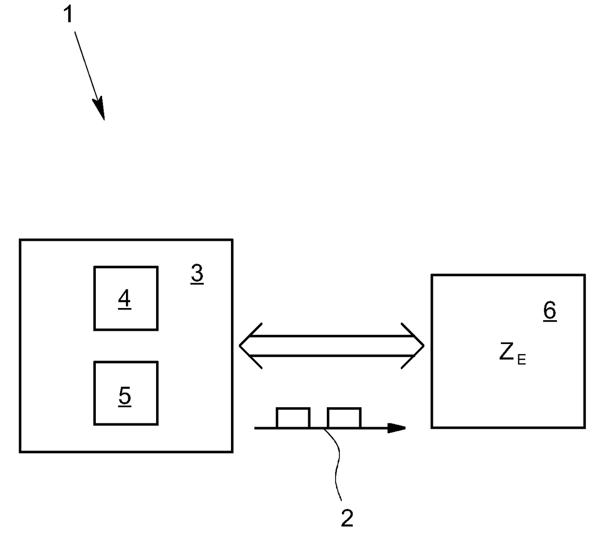
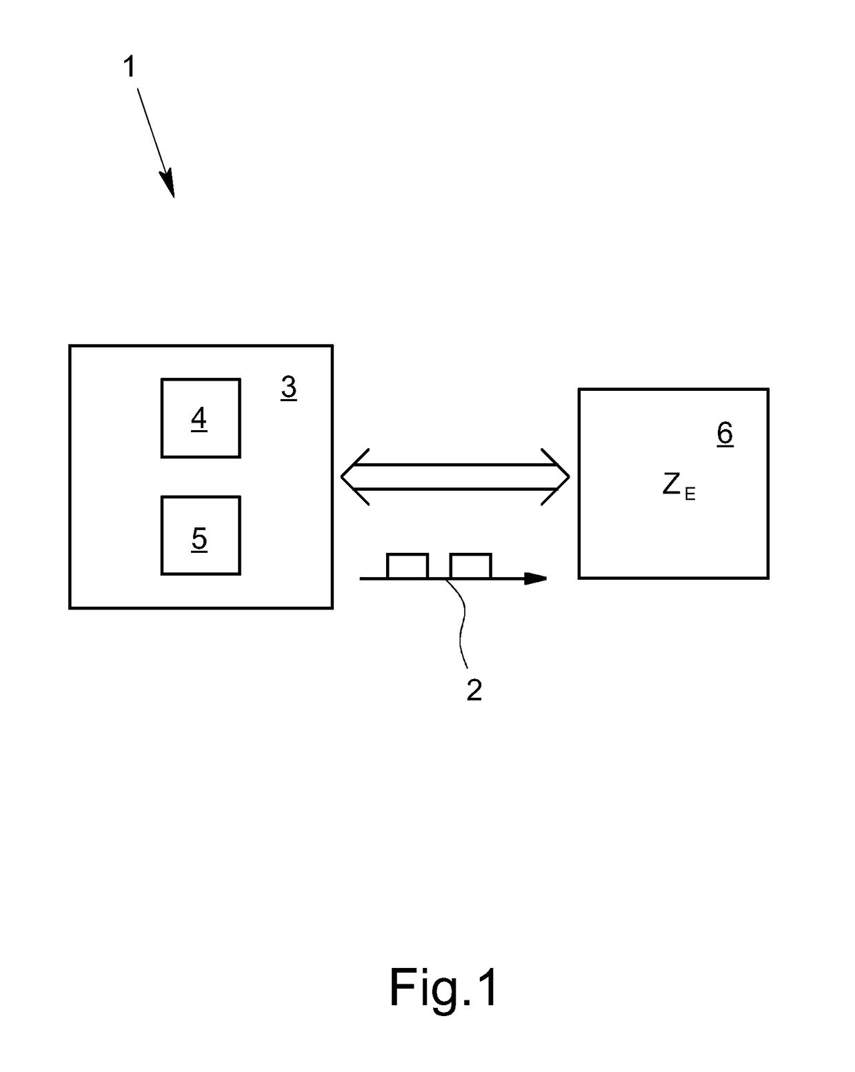
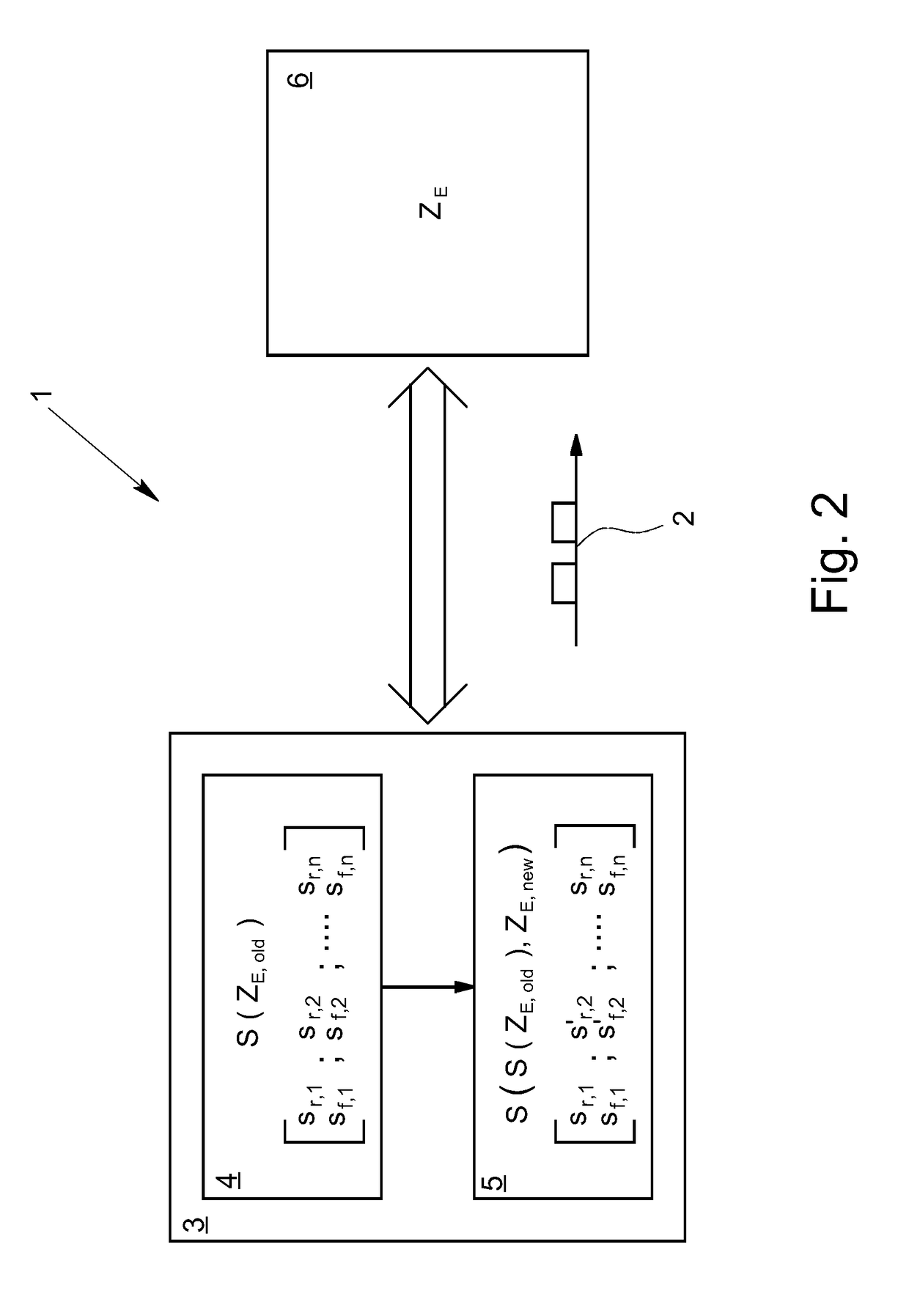
[0030]Shown in FIG. 1 is a known computer-implemented method 1 for calculation and output of control pulses 2 by a control unit 3, and a commensurate control unit 3, wherein the control unit 3 has a first computing unit 4 and a second computing unit 5, and wherein the control pulses 2 are output by the control unit 3 to an internal combustion engine 6.

[0031]In the exemplary embodiment shown, the control unit 3 is an engine control unit with an I / O interface that is not shown in detail and through which the control unit 3 not only outputs signals to influence the internal combustion engine 6—and if applicable other components of a vehicle—but also reads in signals to obtain information about the process to be influenced. The signals may be analog voltages, switching signals, signal patterns (for example, pulse-width modulated signals), or even complex binary data in the form of messages in the protocol of a bus communication. The state data ZE of the engine 6, in particular, are of i...


PUM


Abstract

A computer-implemented method for calculation and output of control pulses by a control unit having a first computing unit and a second computing unit, wherein the control pulses are output by the control unit to an internal combustion engine. The calculation of the control pulses is optimized in that the first computing unit calculates a control pulse pattern with triggering information for multiple future control pulses at a first sampling rate using prior state data of the engine, and transmits the calculated control pulse pattern to the second computing unit, that the second computing unit at a second sampling rate that is greater than the first sampling rate of the first computing unit corrects the triggering information of the control pulses that are currently to be output using current state data of the engine, and that control pulses are output to the engine based on the corrected triggering information.

Description

[0001]This nonprovisional application claims priority under 35 U.S.C. §119(a) to German Patent Application No. 10 2015 101 513.7, which was filed in Germany on Feb. 3, 2015, and which is herein incorporated by reference.BACKGROUND OF THE INVENTION[0002]Field of the Invention[0003]The invention relates to a computer-implemented method for calculation and output of control pulses by a control unit, wherein the control unit has a first computing unit and a second computing unit, and wherein the control pulses are output by the control unit to an internal combustion engine. Moreover, the invention also relates to a control unit in this connection for calculation and output of control pulses to an internal combustion engine, wherein the control unit has a first computing unit and a second computing unit.[0004]Description of the Background Art[0005]Methods for calculation and output of control pulses by a control unit have been known ever since control units, in the form of engine control...

Claims


Application Information

Patent Timeline
Patent Type & Authority Patents(United States)
IPC IPC(8): F02D41/26F02D41/34F02D41/30G05B19/042F02D41/00F02D37/02
CPCF02D41/26F02D41/266F02D41/34G05B19/0421Y02T10/44F02D41/009F02D2250/12G05B2219/25229F02D37/02F02D41/30F02P5/15Y02T10/40
Inventor JUHASZ, LASZLOBERNECK, DIRK
Owner DSPACE DIGITAL SIGNAL PROCESSING & CONTROL ENG
Why Eureka
Try Eureka