Connector

a technology of connecting rods and connectors, applied in the direction of coupling contact members, coupling device connections, incorrect coupling prevention, etc., can solve the problems of increasing the time requirement of docking, excessive angle, and inability to precisely insert the circuit board of the plug, so as to avoid the inner structure damage

Active Publication Date: 2018-10-09
LUXSHARE PRECISION IND SHENZHEN
View PDF24 Cites 17 Cited by
  • Summary
  • Abstract
  • Description
  • Claims
  • Application Information

AI Technical Summary

Benefits of technology

[0011]The invention provides a connector. The connector includes a scoop-proof device. When the connector docks with another connector, the scoop-proof device can effectively prevent the connector from being inserted with an offset angle, thus avoiding the inner-structure damage generated in the docking phase of the two connectors.
[0012]According to another aspect of the present invention, a connector is provided. The connector includes a scoop-proof device which is one or more guides. When the connector is going to share high frequency signals with the docking connector, the guides can guide the connector and the docking connecter to face each other and to be docked straightly. By reducing the occasions that connectors are docked with each other obliquely, the inside terminals are not bumped and damaged as often, thus generally improving the docking quality of the connectors.
[0014]In the present invention, each of the guides has an exposed part exposed from the insulating housing, and the exposed part of each of the guides extends outwardly towards the docking connector and approach a location of the gold fingers on the circuit board, so as to form the guides as a scoop-proof device. The connector and the docking connector are docked together by the guidance of the guides located at the two sides of the insulating housing, so as to prevent the connector from docking with the docking connector with an offset angle. In addition, the guides may also be formed by vertically extending the two sides of the insulating housing of the connector outwardly towards the docking connector, so that the guides is and the insulating housing are formed in one piece, thus generally improves the stability of the guides on the connector.

Problems solved by technology

When connectors are docked together, if the structures of the plug and socket are not designed with a suitable position guiding device, it might be impossible to precisely insert the circuit board of the plug into the cavity of the socket, or there might be an excessive angle.
Not only the situation increases the time requirement of docking, but the general structure of the plug or the socket might also be damaged.
In the foregoing technology, however, the wire connector A100 is guided by only one structure on the guide surface A35, so the accuracy of guiding and matching has not yet achieved a satisfying level.
There still exists the problem that the socket connector may be docked with the wire connector A100 with an excessive angle, in which case the inside terminals of the socket connector are prone to be damaged by the bumping of the wire connector A100, and thus further reduces the life-span of the connector A100.

Method used


Image

  • Connector
  • Connector
  • Connector

Examples


first embodiment

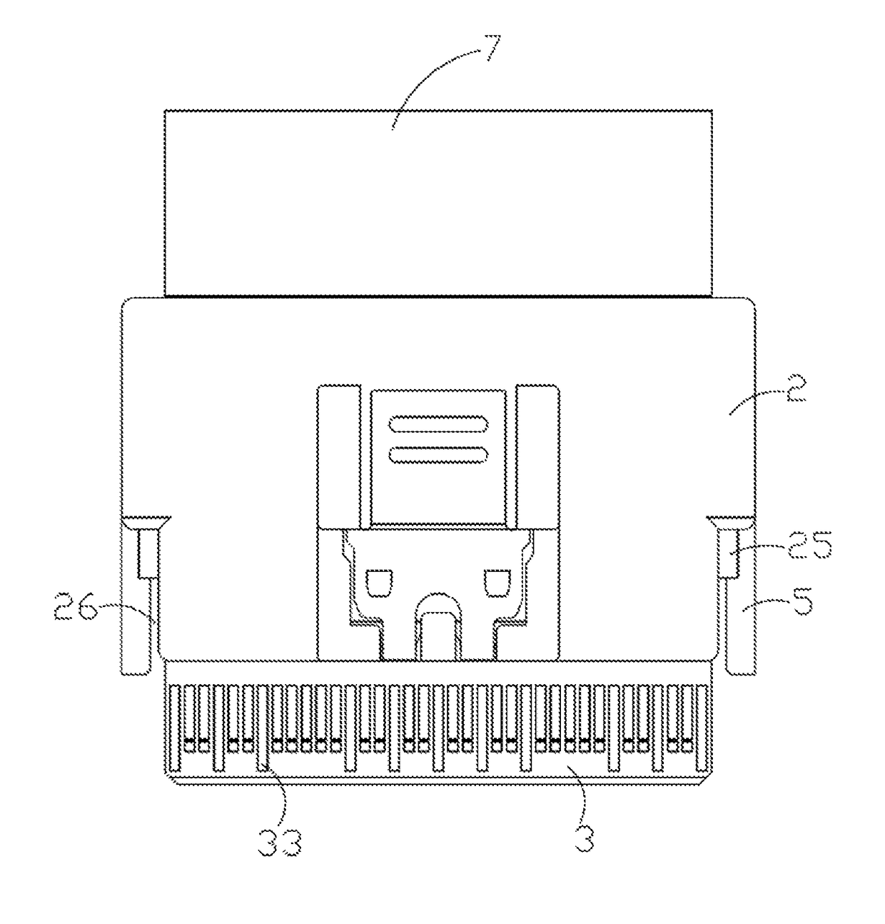
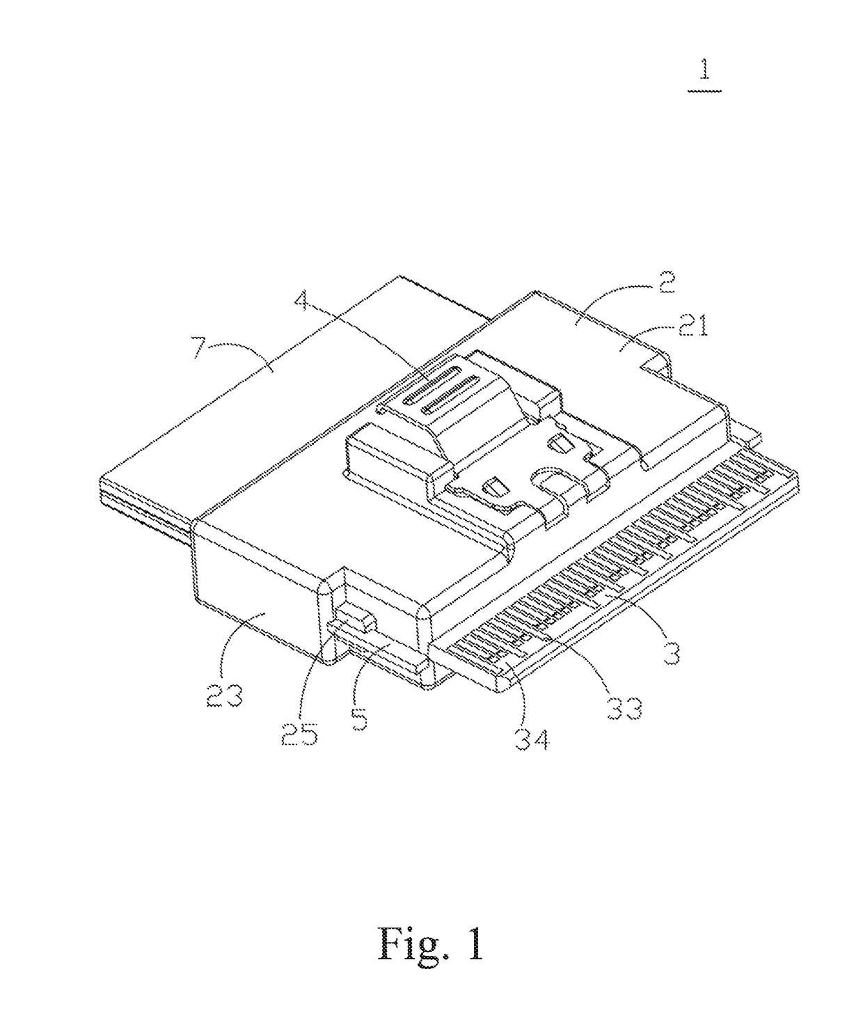
[0031]As shown in FIG. 1 and FIG. 6, a connector is disclosed according to the present disclosure. The connector 1 includes an insulating housing 2, a circuit board 3, and a plurality of first guides 5, wherein the circuit board 3 is embedded in the insulating housing 2 and a docking connector 8 may be inserted in the connector 1.

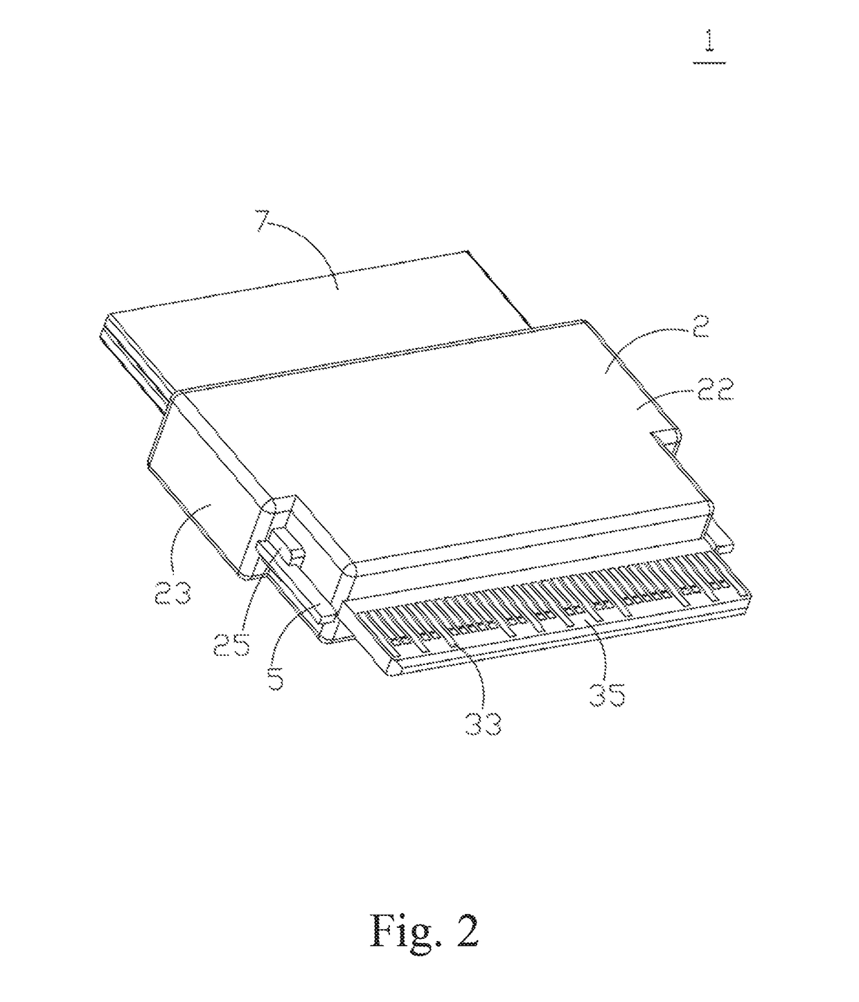
[0032]As shown in FIG. 2 to FIG. 7, in the first embodiment of the present disclosure, the connector 1 includes an insulating housing 2, a circuit board 3, a flexible piece 4, and a plurality of first guides 5. The insulating housing 2 is made of an insulating material and the insulating housing 2 includes a top surface 21, a bottom surface 22, and a plurality of sides 23. Each of the sides 23 respectively connects to the top surface 21 and the bottom surface 22 to form a closed rectangular house. The circuit board 3 is also made of an insulating material. The circuit board 3 has a front end 31, a back end 32 and a plurality of gold fingers 33, wherein the ...

second embodiment

[0037]As shown in FIG. 8 to FIG. 11, in the present invention, second guides 9 may also be formed and protruded by broadening opposite sides of the insulating housing 2 of the connector 1 and vertically extending the sides outwardly towards a docking connector (not shown). The second guides 9 are L-shape structures herein. The second guides 9 with L-shape structures are disposed symmetrically that they face towards each other in regards of the sides of the insulating housing 2, the disposing location and the shape of the second guides 9 may be varied with practical demand, the FIGURES disclosed herein are only a preferred embodiment and not intended to limit the scope of the present invention. Since the second guides 9 and the insulating housing 2 are formed in one piece, the stability of the second guides 9 on the connector 1 is generally improved.

[0038]In comparison with the prior art, by using the guides in the connector to match with the docking connector and as a scoop-proof de...


PUM


Abstract

A connector includes an insulating housing, a circuit board, a flexible piece, and a plurality of guides. The circuit board has a front end configured to dock with a docking connector, a back end distal to the front end, and a plurality of gold fingers disposed at the front end. The back end is embedded in the insulating housing and the front end is extended outwardly from the insulating housing such that each gold finger is exposed at a surface of the circuit board. The flexible piece is installed at a top surface of the insulating housing. The flexible piece is used to engage with the docking connector. Each gold finger can be electrically connected to the docking connector. Each guide is disposed at two opposite sides of the insulating housing. Each guide extends outwardly towards the docking connector.

Description

RELATED APPLICATIONS[0001]This application claims priority to Taiwan Application Serial Number 106201345, filed Jan. 23, 2017, which is herein incorporated by reference.BACKGROUND[0002]Technical Field[0003]The present invention relates to a connector including a scoop-proof device and more particular to a connector includes a SAS (Serial Attached SCSI) transmission interface.[0004]Description of Related Art[0005]With the rapid change of science and technology in the recent years and the high speed progression of cloud technology, there follows a great amount of data to be transported. Using connectors to achieve the data transportation has already become an indispensable and crucial technology at the time. From the early SCSI (Small Computer System interface) to the nowadays SAS (Serial Attached SCSI, serial-SCSI), with respect to the need of high speed data accessing, serial technology overcomes the bottleneck of conventional parallel technology, and provides a much faster signal t...

Claims


Application Information

Patent Timeline
Patent Type & Authority Patents(United States)
IPC IPC(8): H01R13/64H01R13/6582H01R13/6466H01R13/422H01R12/50H01R13/26
CPCH01R13/6466H01R13/26H01R23/68H01R13/6582H01R13/4226H01R12/721H01R13/64H01R24/60H01R12/00
Inventor HUANG, KUO-HUAHSUEH, CHENG-HSIANG
Owner LUXSHARE PRECISION IND SHENZHEN
Why Eureka
Try Eureka