
Medium voltage wind power generation system and power generation method using the same

a wind power generation system and medium voltage technology, applied in the direction of electric generator control, machines/engines, mechanical equipment, etc., can solve the problems of low transmission efficiency, increased space where the converter is mounted, and increased diameter of the tower bottom, so as to increase the electric power transmission efficiency of the system, reduce the cost and volume of the system, and reduce the capacity

Active Publication Date: 2018-10-23
DELTA ELECTRONICS (SHANGHAI) CO LTD
View PDF10 Cites 0 Cited by
  • Summary
  • Abstract
  • Description
  • Claims
  • Application Information

AI Technical Summary

Benefits of technology

[0033]The medium voltage wind power generation system according to the present invention, which uses low-voltage power devices and boosting transformers of small capacity, can achieve the application of a medium voltage power generation system, increase the electric power transmission efficiency of the system, and reduce the cost and volume of the system. The line side converters and rotor side converters among the converters are of the same capacity, thereby facilitating the modular design and the arrangement of installations. Stator windings output the medium voltage alternating current to boosting transformers, thereby saving the cost of transmission cables and reducing the loss caused during power transmission.

Problems solved by technology

In the existing doubly-fed wind power generation system, the alternating current outputted from a doubly-fed power generation device goes through two-stage booster systems, so the transmission efficiency is low and extra electric power will be lost.
However, the diameter of the tower bottom, that is, the space where the converter is mounted, does not increase as the power multiplies.
It is more and more difficult to design and mount the converter.
With the increase in power, the current increases in proportion, and the number and capacity of the transmission cables needed increase in proportion, resulting increased construction costs of the existing doubly-fed wind power generation system.

Method used


Image

  • Medium voltage wind power generation system and power generation method using the same
  • Medium voltage wind power generation system and power generation method using the same
  • Medium voltage wind power generation system and power generation method using the same

Examples


first embodiment

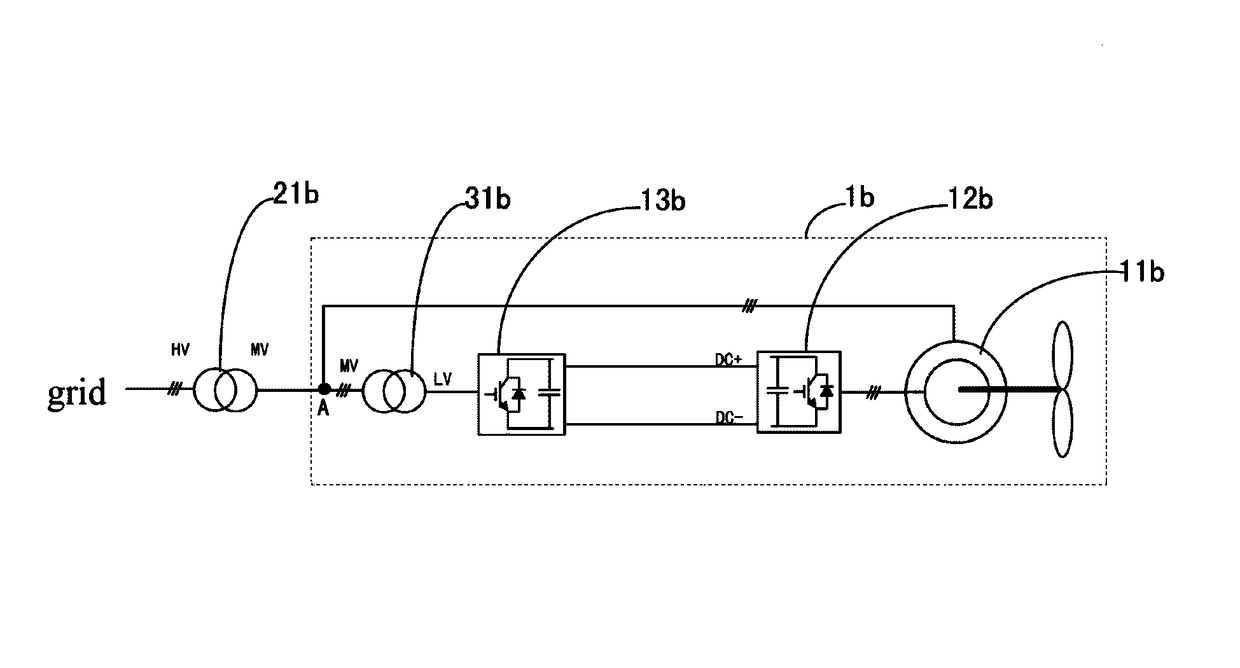
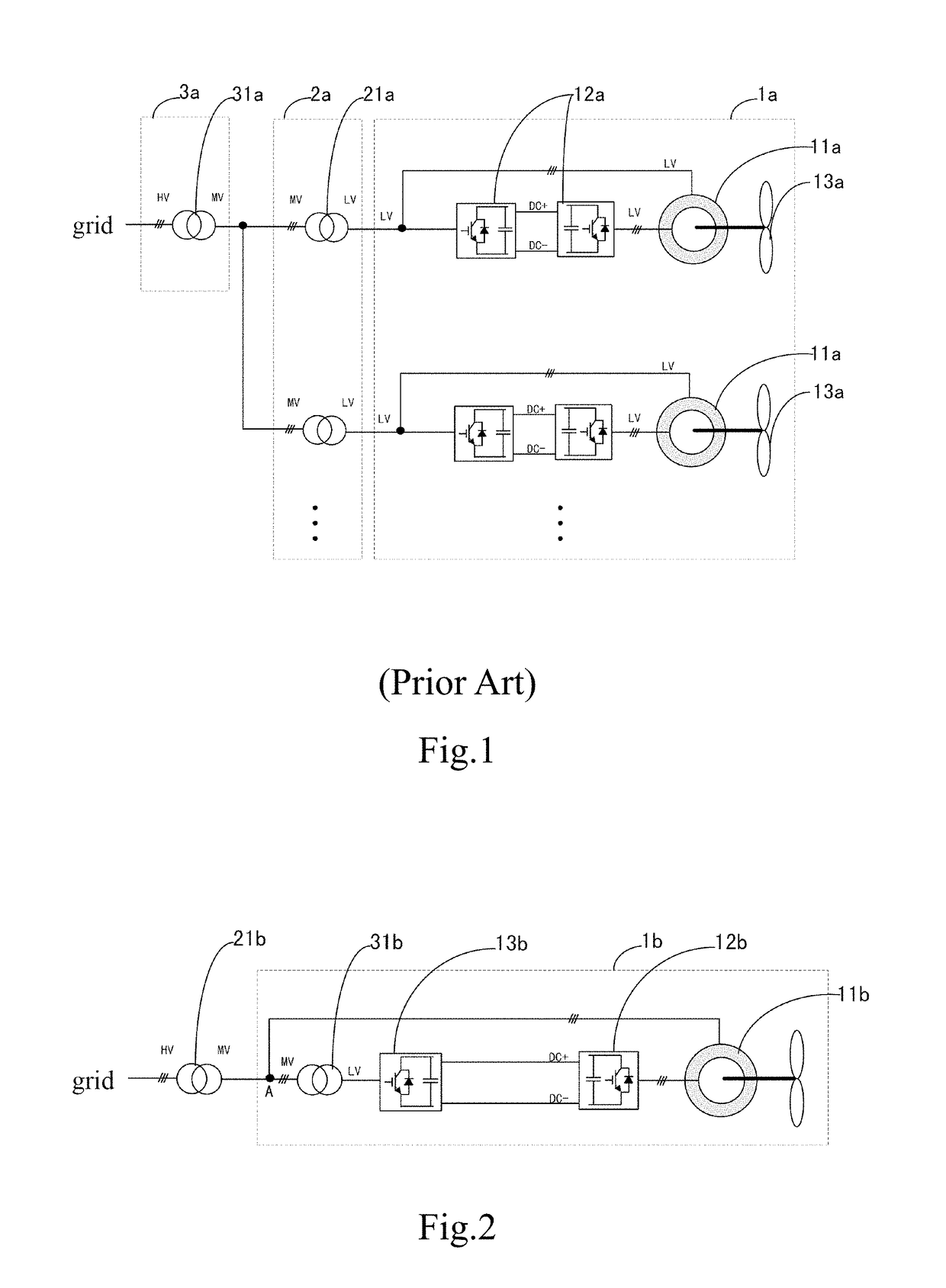
[0044]Please refer to FIG. 2, which is a schematic view showing the structure of the medium voltage wind power generation system according to the present invention. As shown in FIG. 2, the medium voltage wind power generation system of the present invention comprises a doubly-fed wind power generation device 1b and a first boost device 21b. The first boost device 21b has a medium voltage side MV and a high voltage side HV, and the high voltage side HV of the first boost device 21b is electrically connected to a grid.

[0045]Further, the doubly-fed wind power generation device 1b comprises a wind generator 11b, a rotor side converter 12b, a line side converter 13b and a second boost device 31b. The wind generator 11b comprises a stator winding and rotor windings. The stator winding is coupled to the medium voltage side MV of the first boost device 21b. The rotor side converter 12b is coupled to the rotor windings. One end of the line side converter 13b is coupled to the rotor side conv...

second embodiment

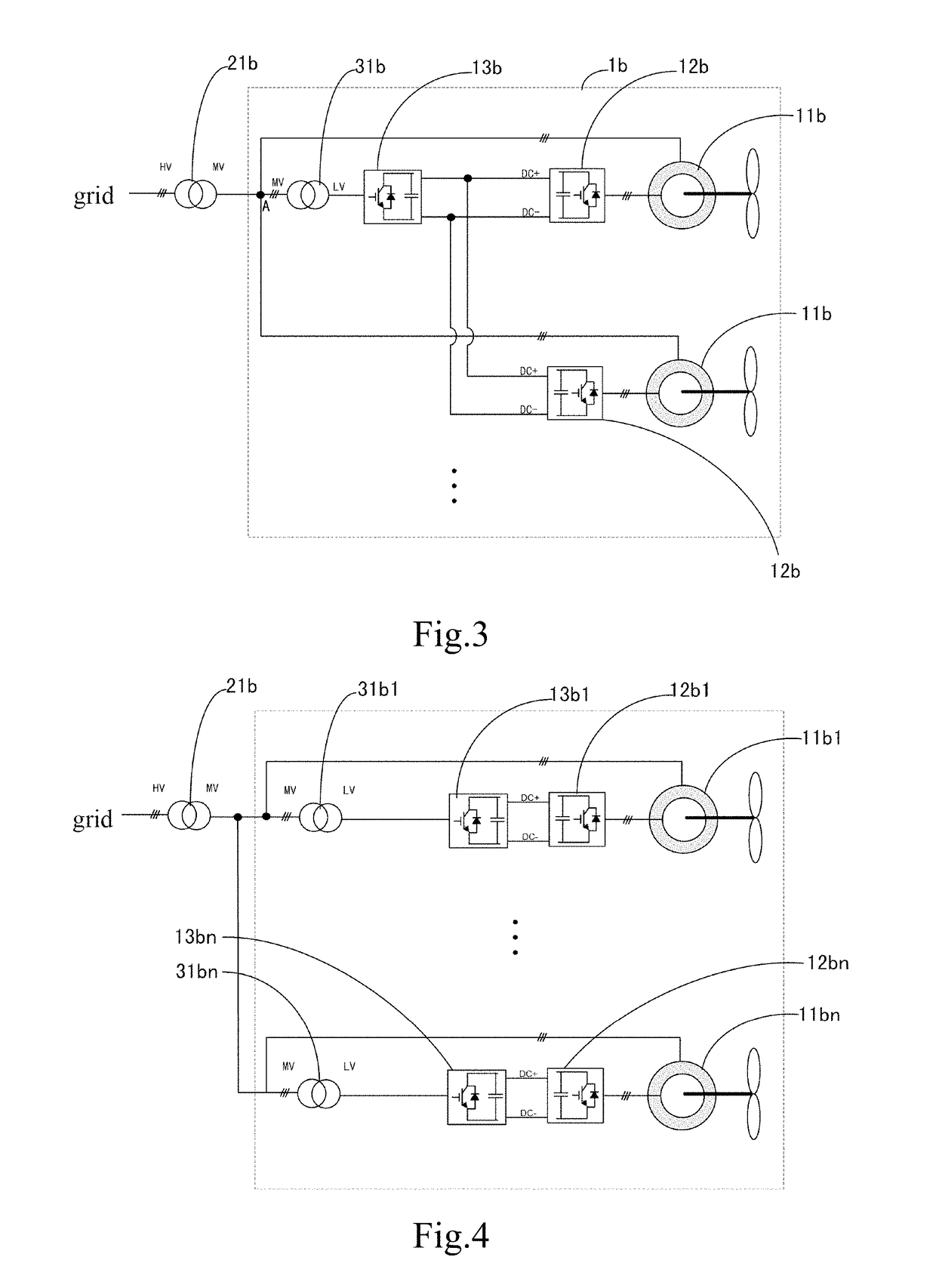
[0048]Refer to FIG. 3, which is a schematic view showing the structure of the medium voltage wind power generation system according to the present invention. The medium voltage wind power generation system shown in FIG. 3 and that shown in FIG. 2 follow the same principle, so the things that FIG. 2 shares in common with FIG. 3 will not be repeated here, and the differences between them will be descried hereinafter. The doubly-fed wind power generation device 1b of the medium voltage wind power generation system shown in FIG. 3 comprises a plurality of wind generators 11b, a plurality of rotor side converters 12b, and a plurality of line side converters 13b. The stator windings of the plurality of wind generators 11b are electrically connected to the medium voltage side MV of the first boost device 21b. The rotor windings of the plurality of wind generators 11b are correspondingly electrically connected to the plurality of rotor side converters 12b in a one-to-one ratio; and each of ...

third embodiment

[0054]Refer to FIG. 4, which is a schematic view showing the structure of the medium voltage wind power generation system according to the present invention. The medium voltage wind power generation system shown in FIG. 4 differs from that shown in FIG. 3 in that the medium voltage wind power generation system shown in FIG. 4 further comprises a plurality of second boost devices 31b1 to 31bn and a plurality of line side converters 13b1 to 13bn. The medium voltage sides MV of the plurality of second boost devices 31b1 to 31bn are electrically connected to the medium voltage side MV of the first boost device 21b. The low voltage sides LV of the plurality of second boost devices 31b1 to 31bn are correspondingly electrically connected to the plurality of line side converters 13b1 to 13bn in a one-to-one ratio. The plurality of line side converters 13b1 to 13bn are correspondingly electrically connected to the plurality of rotor side converters 12b1 to 12bn in a one-to-one ratio. The plu...


PUM


Abstract

A medium voltage wind power generation system comprises a first boost device and a wind power generation device; the first boost device has a medium voltage side and a high voltage side, and the high voltage side of the first boost device is electrically connected to a grid; the wind power generation device comprises wind generators, rotor side converters and line side converters; the wind generators comprise stator windings and rotor windings; the stator windings are coupled to the medium voltage side of the first boost device; the rotor side converters are coupled to the rotor windings; one end of the line side converters are coupled to the rotor side converters, and the other end thereof is coupled to the medium voltage side of the first boost device via a second boost device.

Description

CROSS-REFERENCE TO RELATED APPLICATIONS[0001]This non-provisional application claims priority under 35 U.S.C. § 119(a) on Patent Application No. 201610625604.4 filed in P.R. China on Aug. 2, 2016, the entire contents of which are hereby incorporated by reference.[0002]Some references, if any, which may include patents, patent applications and various publications, may be cited and discussed in the description of this invention. The citation and / or discussion of such references, if any, is provided merely to clarify the description of the present invention and is not an admission that any such reference is “prior art” to the invention described herein. All references listed, cited and / or discussed in this specification are incorporated herein by reference in their entireties and to the same extent as if each reference was individually incorporated by reference.TECHNICAL FIELD[0003]The present invention relates to an electric power technology, and particularly to a wind power generati...

Claims


Application Information

Patent Timeline
Patent Type & Authority Patents(United States)
IPC IPC(8): F03D9/00H02K7/18H02P9/00H02J3/38F03D9/25H02P9/04H02P101/15
CPCF03D9/255H02J3/386H02P9/007H02K7/183H02P2101/15H02J2300/28H02J3/381H02J3/46Y02E10/76Y02E10/72
Inventor WANG, CHANGYONGLU, FEI
Owner DELTA ELECTRONICS (SHANGHAI) CO LTD
Learn More