Thermal module

a technology of thermal modules and heat exchangers, applied in the direction of lighting and heating apparatus, basic electric elements, semiconductor devices, etc., can solve the problems of non-uniform distribution of heat over the surface, heat generated by the miniaturized components of the electronic apparatus, etc., to achieve the maximum heat transfer (qmax) of the heat pipe, increase the capacity of the compartment, and increase the amount of working fluid

Active Publication Date: 2018-10-23
ASIA VITAL COMPONENTS SHENZHEN CO LTD
View PDF10 Cites 0 Cited by
  • Summary
  • Abstract
  • Description
  • Claims
  • Application Information

AI Technical Summary

Benefits of technology

[0011]It is still a further object of the present invention to provide the above thermal module in which multiple heat pipes are respectively connected to the independent compartments, whereby multiple vapor-liquid circulations of working fluids independently take place within the independent compartments and the heat pipe chambers to transfer heat without interfering with each other.
[0012]It is still a further object of the present invention to provide the above thermal module, which is able to provide best heat dissipation effect for a heat source over which the heat is non-uniformly distributed.
[0013]It is still a further object of the present invention to provide the above thermal module in which the independent compartments communicate with the heat pipe chambers of the heat pipes to enlarge the capacity of the compartments so as to increase the amount of the working fluid contained in the compartments, whereby the maximum heat transfer (Qmax) of the heat pipe is increased.

Problems solved by technology

The heat generated by the miniaturized components of the electronic apparatus has become a major obstacle to having better performance of the electronic apparatus and system.
However, the heat may be non-uniformly distributed over the surface.

Method used


Image

  • Thermal module
  • Thermal module
  • Thermal module

Examples


Embodiment Construction

[0035]The embodiments of the present invention will be described hereinafter with reference to the drawings, wherein the same components are denoted with the same reference numerals.

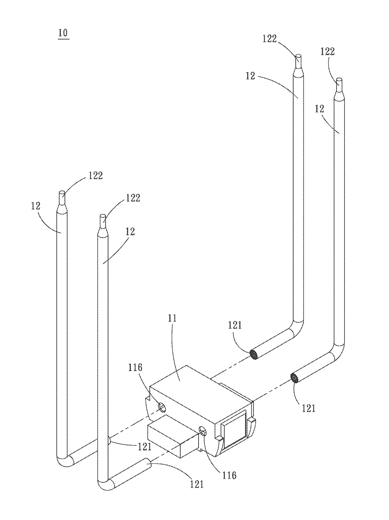
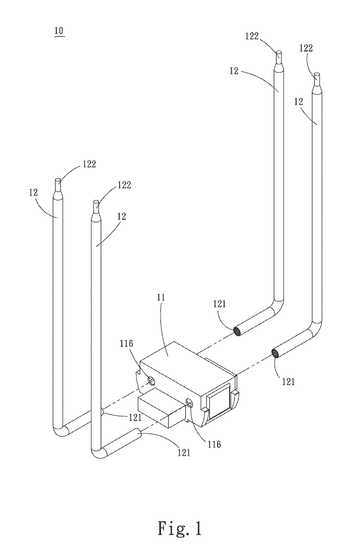
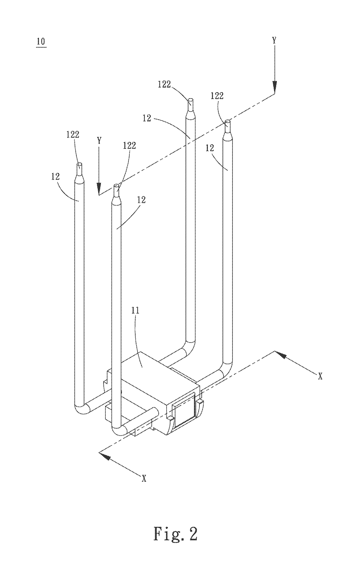
[0036]Please refer to FIGS. 1 to 4. FIG. 1 is a perspective exploded view of the present invention. FIG. 2 is a perspective assembled view of the present invention. FIG. 3 is a sectional view taken along line X-X of FIG. 2. FIG. 4 is a sectional view taken along line Y-Y of FIG. 2. The thermal module 10 of the present invention includes a housing 11 having several independent compartments 111a˜111d not in communication with each other. Each compartment 111a˜111d communicates with an open end of at least one heat pipe. The open end communicates with a heat pipe chamber in the heat pipe, whereby the independent compartments 111a˜111d communicate with the heat pipe chambers.

[0037]The housing 1 is made of a material with excellent thermal conductivity, such as metal or plastic material. The housing 1 has a t...


PUM


Abstract

A thermal module includes a housing having multiple independent compartments not in communication with each other. Each compartment communicates with an open end of at least one heat pipe. The open end communicates with a heat pipe chamber in the heat pipe, whereby the independent compartments communicate with the heat pipe chambers.

Description

BACKGROUND OF THE INVENTION[0001]1. Field of the Invention[0002]The present invention relates generally to a thermal module, and more particularly to a thermal module capable of providing excellent heat dissipation effect for a heat source over which the heat is non-uniformly distributed.[0003]2. Description of the Related Art[0004]There is a trend to develop thinner and thinner electronic apparatuses nowadays. The ultra-thin electronic apparatus includes miniaturized components. The heat generated by the miniaturized components of the electronic apparatus has become a major obstacle to having better performance of the electronic apparatus and system. In order to solve the heat dissipation problem of the components in the electronic apparatuses, various vapor chambers and heat pipes with better heat conduction performance have been developed.[0005]The vapor chamber has a rectangular housing and capillary structures formed on inner wall face of the chamber of the housing. A working f...

Claims


Application Information

Patent Timeline
Patent Type & Authority Patents(United States)
IPC IPC(8): F28D15/04F28D15/02H01L23/427
CPCF28D15/04F28D15/0275H01L23/427H01L2924/0002H01L2924/00
Inventor YANG, HSIU-WEI
Owner ASIA VITAL COMPONENTS SHENZHEN CO LTD
Why Eureka
Try Eureka