Plate heat exchanger

a technology of heat exchanger and plate, which is applied in the direction of indirect heat exchangers, lighting and heating apparatus, and separation processes, etc., can solve the problems of difficult control of the flow inside the first inlet channel, insufficient heat exchanger efficiency, so as to reduce the number of heat exchanger plates and the amount of cooling agent. , to achieve the effect of improving the efficiency of the plate heat exchanger, reducing the number of heat exchanger plates and the amount of cooling

Inactive Publication Date: 2018-10-23
ALFA LAVAL CORP AB
View PDF47 Cites 0 Cited by
  • Summary
  • Abstract
  • Description
  • Claims
  • Application Information

AI Technical Summary

Benefits of technology

[0008]The object of the present invention is to provide an improved plate heat exchanger remedying the problems mentioned above. Especially it is aimed at a plate heat exchanger, which allows a better control and distribution of the supply of the first fluid, such as a cooling agent, between the individual plate interspaces to thereby improve the efficiency of the plate heat exchanger. A further object of the invention is to provide a plate heat exchanger, which even allows a reduction of the number and size of the port holes. Another purpose is to allow a reduction of the number heat exchanger plates and also the amount of cooling agent,

Problems solved by technology

It is difficult to provide an optimal distribution of the fluid to the different plate interspaces in such a way that e.g. an optimized quantity of fluid is supplied and flows through each plate interspace.
First of all it is very hard to control the flow inside the first inlet channel.
There is always a risk of that the energy content of the inserted fluid is too high, whereby a part of the flow supplied to the inlet channel via its inlet port will meet the rear end of the inlet channel and be reflected thereby in the opposite direction.
Thereby the flow in the inlet channel is very chaotic and hard to predict and control.
Thereby it is hard to optimize the efficiency of the plate heat exchanger.
The available acting space for flow optimization is thereby restricted.
Generally the efficiency of a plate heat exchanger at part load is a raising issue for the purpose of reducing the energy consumption.
Further, an evaporator system is typically only operating at full capacity for 3% of the time, while most evaporators are designed and tuned for a full capacity operation duty.
However, during normal operation the work load varies greatly and it hardly reflects the fictive conditions used for the standard.

Method used


Image

  • Plate heat exchanger
  • Plate heat exchanger
  • Plate heat exchanger

Examples


Embodiment Construction

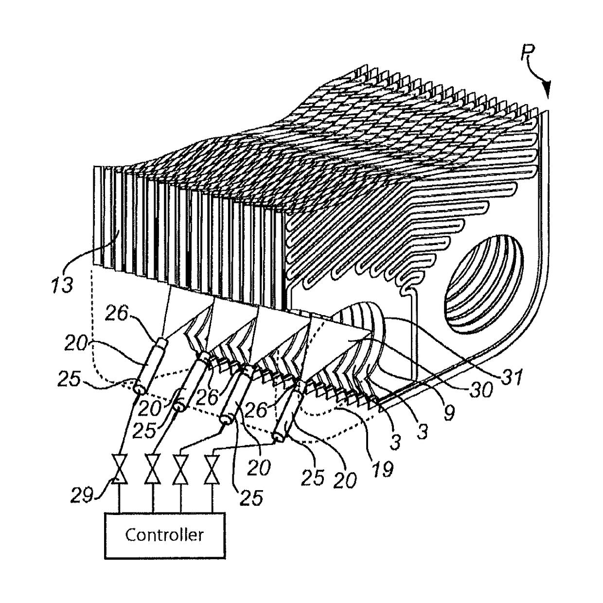
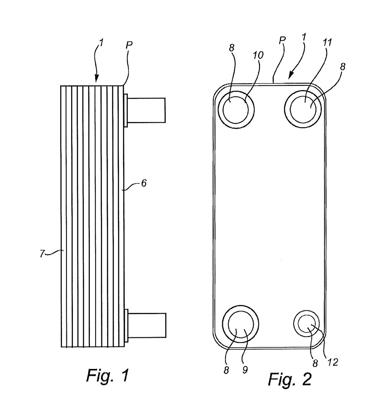
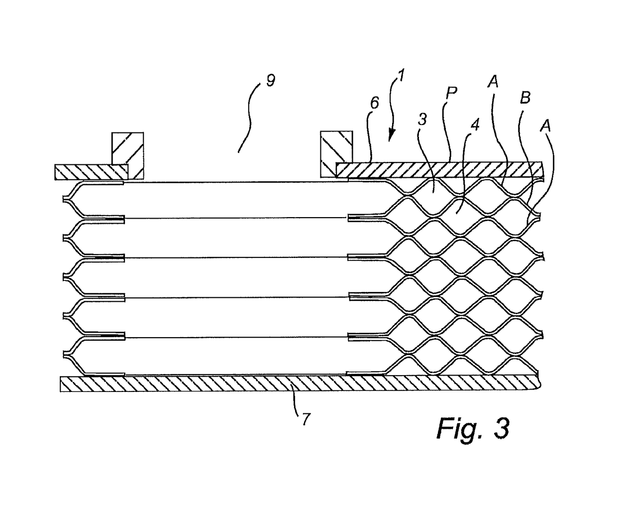
[0047]FIGS. 1 to 3 disclose a typical example of a plate heat exchanger 1. The plate heat exchanger 1 includes a plate package P, which is formed by a number of compression molded heat exchanger plates A, B, which are provided side by side of each other. The plate heat exchanger 1 comprises two different types of heat exchanger plates, which in the following are called the first heat exchanger plates A, see FIGS. 3 and 4, and the second heat exchanger plate B, see FIGS. 3 and 5. The plate package P includes substantially the same number of first heat exchanger plates A and second heat exchanger plates B. As is clear from FIG. 3, the heat exchanger plates A, B are provided side by side in such a way that a first plate interspace 3 is formed between each pair of adjacent first heat exchanger plates A and second heat exchanger plates B, and a second plate interspace 4 between each pair of adjacent second heat exchanger plates B and first heat exchanger plates A.

[0048]Every second plate...


PUM


Abstract

The invention relates to a plate heat exchanger including a plate package, which includes a number of first and second heat exchanger plates which are joined to each other and arranged side by side in such a way that first and second plate interspaces are formed. At least two injectors are provided, each injector being arranged to supply a first fluid to at least one of the first plate interspaces in the at least one plate package and at least one valve is arranged to control the supply of the first fluid to the at least two injectors.

Description

TECHNICAL FIELD[0001]The present invention refers generally to the fluid supply to a plate heat exchanger.BACKGROUND ART[0002]The present invention refers generally to a plate heat exchanger, in particular a plate heat exchanger in the form of an evaporator, i.e. a plate heat exchanger designed for evaporation of a fluid, i.e. a cooling agent, in a circuit for various applications, such as air conditioning, cooling systems, heat pump systems, etc.[0003]A plate heat exchanger, typically includes a plate package, with a number of first heat exchanger plates and a number of second heat exchanger plates, which are joined to each other and arranged side by side in such a way that a first plate interspace is formed between each pair of adjacent first heat exchanger plates and second heat exchanger plates and a second plate interspace between each pair of adjacent second heat exchanger plates and first heat exchanger plates. The first plate interspaces and the second plate interspaces are ...

Claims


Application Information

Patent Timeline
Patent Type & Authority Patents(United States)
IPC IPC(8): F28F13/08F28F27/02F25B39/02F28D1/03F28D9/02F28D9/00B01D1/22F28F9/02F28D21/00
CPCF28F13/08F25B39/022F25B39/028F28D1/0325F28D9/005F28D9/0043F28D9/02F28F9/02F28F9/027F28F9/0273F28F27/02B01D1/221F28F9/0268F25B2500/01F28D2021/0071F28D2021/0085
Inventor BERTILSSON, KLASNYANDER, ANDERSBERMHULT, ROLF
Owner ALFA LAVAL CORP AB
Why Eureka
Try Eureka