
Planetary roller extruder with planet spindles and contact ring

a technology of contact ring and planetary roller, which is applied in the direction of transportation and packaging, rotary stirring mixers, food shaping, etc., can solve the problems of planetary roller extruders that are never fully filled with extrusion material, roller parts cannot be withstanded, and the planetary roller extruders are difficult to prevail

Active Publication Date: 2018-10-30
ENTEX RUST & MITSCHKE
View PDF18 Cites 4 Cited by
  • Summary
  • Abstract
  • Description
  • Claims
  • Application Information

AI Technical Summary

Benefits of technology

[0049]As far as after the dispersion and homogenization of the melt in the planetary roller extruder a degassing will become necessary and / or desired. It may be possible that the planetary spindles will receive a lower mixing effect in the range of the requested degassing in order to allow the gas a more and better opportunity to exit out of the melt. In the planetary roller extruder this can be produced by the reduction of the number of spindles and / or by a special design of the planetary spindles. A possible special design is the reduction of the number of teeth at the planetary spindles.
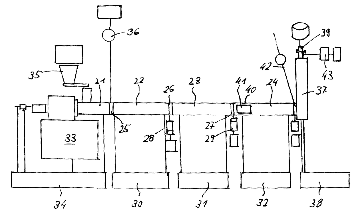
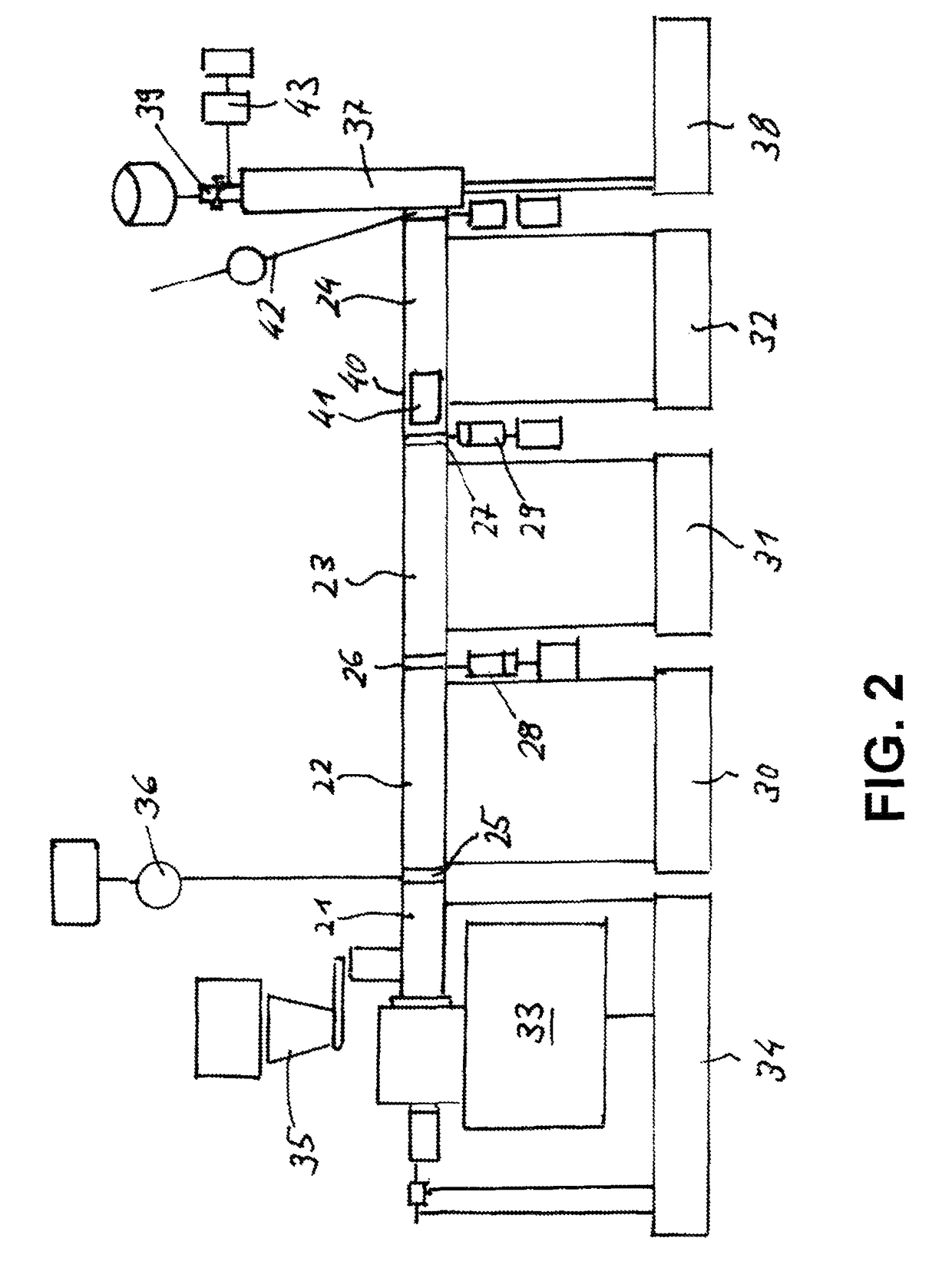
[0051]Optionally the extrusion material will be fed also into a drivable single-screw extruder being speed-independent of the planetary roller extruder. Then this in-line single-screw extruder can operate at lower speed so that the extrusion material can degas optimally before the discharge of out the line.
[0052]As far as still at another position of the extrusion line, e.g. at the feeding part and / or at another extruder section / module and / or between different extruder sections / modules, a degassing is scheduled, all or substantially all or most or some degassing locations can mutually be connected to one gas removal system. In at least one possible embodiment of the present application, a pump is located in the gas removal system by which a negative pressure can be produced in the degassing line. Thereby it is possible to heat all or substantially all or most or some degassing lines so that melt particles, which are entrained by the escaping gas, do not clog the degassing line.
[0058]However, the path accuracy can be helpful at the assembly or disassembly or rather the change of planetary spindles. Due to the substantially exact or approximate track system the planetary spindles can after the removal of the stop ring without the normal manual support partly be moved out of the housing without the risk—like at other drives—that the planetary spindles rush out and personnel and equipment will come to harm. As soon as the planetary spindles protrude far enough from the housing the planetary spindles can be grasped by hand and can be turned out between housing and central spindle. The assembly will be executed in reverse direction and corresponding advantages will be given. Anyhow, torque motors have up to now not yet be used for planetary roller extruders which are anyway very complex. This may be because it had not been realized how by means of the torque motors the assembly and disassembly of the planetary spindles can be facilitated.
[0062]Torque motors are found in different construction types, as permanent excited (brushless) DC-motors as switched reluctance motors as asynchronous motors as external rotor motor (stator inside, rotor outside) with the possibility of a, in at least one possible embodiment, high torque as internal rotor motor (stator outside, rotor inside) in one possible embodiment the construction type “external rotor motor” will be used for the increase of speed as per the present application, a water-cooling for the motors as well. It will be favorable if the planetary roller extruder as well has a water-cooling which then can be combined with the motor cooling.

Problems solved by technology

Therefore it is be difficult for the planetary roller extruders to prevail over the single-screw extruders and twin-screw extruder in spite of significant process advantages.
The different filling results from the fact that planetary roller extruders are never fully filled with extrusion material.
There is a possible expected risk that the planetary roller parts can no longer withstand the increasing load resulting from an increased speed and that the planetary spindles even could jump out of the toothing and could be destroyed or damage the toothing of the other planetary roller parts.
Thereby the drives are normally designed to the required and / or desired speeds, so that an increase of the speeds with the existing drives is considerably limited.
Nevertheless, these speeds cannot be used as guideline for the planetary roller extruders.
The expert may fear that the sole holding of the rotating planetary spindles by means of their teeth in the toothing of the central spindle and in the toothing of the housing respectively will not be suitable with regard to high speeds.
Furthermore, a depletion appears at a change of material (e.g.: the color of the extrusion material shall be changed) or when cleaning the extruder (e.g.: at operation end molten plastic will be discharged out of the extruder as otherwise it will become solid which will cause extraordinary difficulties when restarting the operation.
In any case predominate by far the opinions which in total come to a loss of efficiency degree.
Then the energy consumption is of inferior importance.
Due to the substantially exact or approximate track system the planetary spindles can after the removal of the stop ring without the normal manual support partly be moved out of the housing without the risk—like at other drives—that the planetary spindles rush out and personnel and equipment will come to harm.
Anyhow, torque motors have up to now not yet be used for planetary roller extruders which are anyway very complex.

Method used


Image

  • Planetary roller extruder with planet spindles and contact ring
  • Planetary roller extruder with planet spindles and contact ring
  • Planetary roller extruder with planet spindles and contact ring

Examples


Embodiment Construction

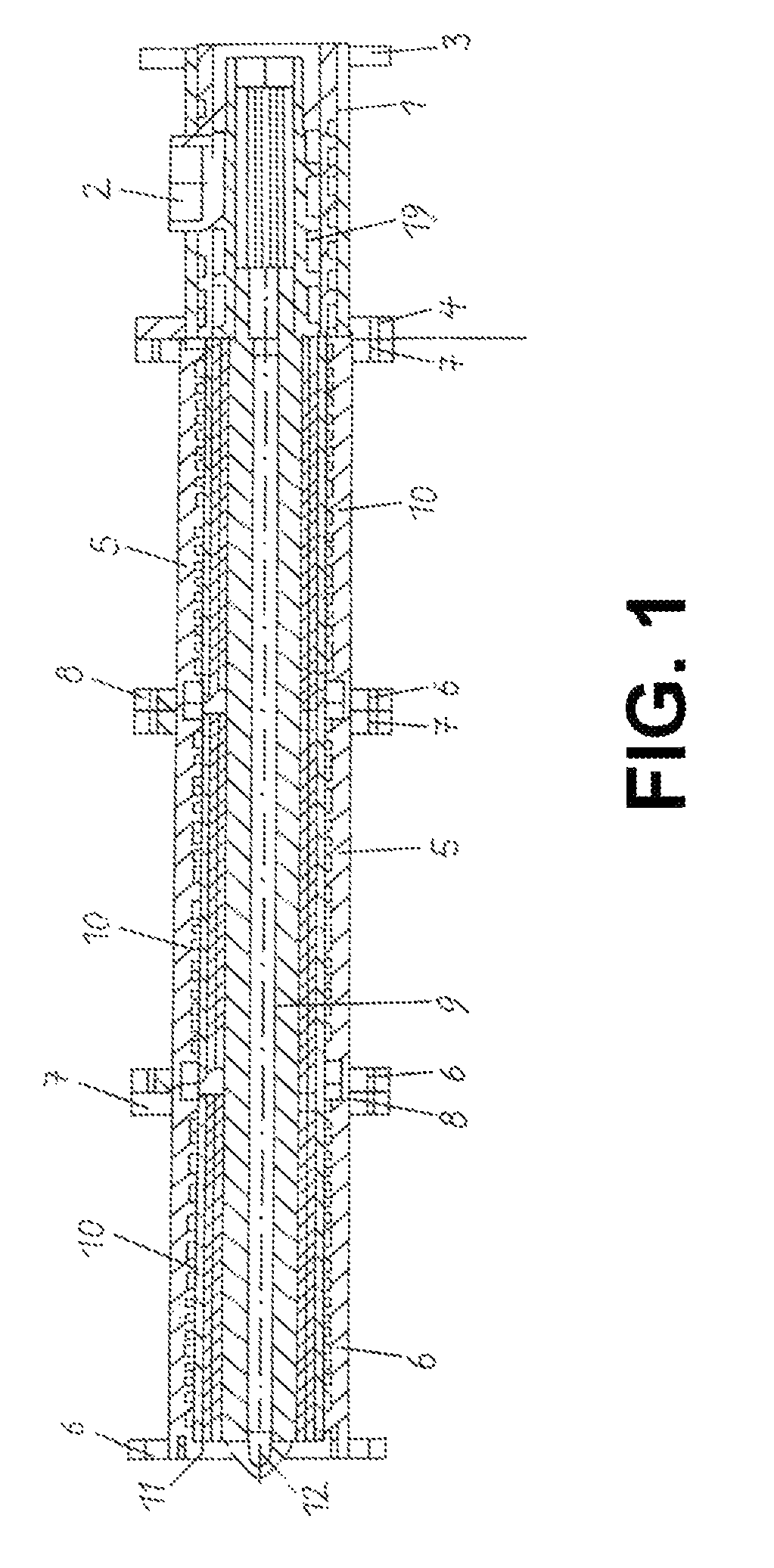
[0068]FIG. 1 shows an extruder with an overlong planetary roller part 11 and a feeding screw 1. The planetary roller part is composed of three planetary roller extruder modules with a conjoint central spindle 9. Each module comprises an outer housing 5 in pipe shape which shows flanges 6 and 7 at both ends. At the flanges 6 and 7 the modules are screwed together. Thereby the housings 5 will be centered by means of cantering rings. The cantering rings are inserted into corresponding recesses of the housing flanges.

[0069]To each planetary roller extruder module belongs also a liner. The liner is located inside in housing 5. During assembly the liners will be inserted into the housings. In at least one possible embodiment of the present application, this is done before the screwing of the flanges 6 and 7. For this the cantering rings are furnished with a boring which is equal to the boring of the housing.

[0070]Between the liners there is one stop ring 8 each located. The stop ring hold...


PUM

PropertyMeasurementUnit
pitch diameteraaaaaaaaaa

Abstract

A planetary roller extruder with planetary spindles and stop ring. The abstract of the disclosure is submitted herewith as required by 37 C.F.R. § 1.72(b). As stated in 37 C.F.R. § 1.72(b): A brief abstract of the technical disclosure in the specification must commence on a separate sheet, preferably following the claims, under the heading “Abstract of the Disclosure.” The purpose of the abstract is to enable the Patent and Trademark Office and the public generally to determine quickly from a cursory inspection the nature and gist of the technical disclosure. The abstract shall not be used for interpreting the scope of the claims. Therefore, any statements made relating to the abstract are not intended to limit the claims in any manner and should not be interpreted as limiting the claims in any manner.

Description

CONTINUING APPLICATION DATA[0001]This application is a Continuation-In-Part application of International Patent Application No. PCT / 2012 / 005318, filed on Dec. 21, 2012, which claims priority from Federal Republic of Germany Patent Application No. 10 2012 008 170.7 filed on Apr. 26, 2012. International Patent Application No. PCT / 2012 / 005318 was pending as of the filing date of this application. The United States was an elected state in International Patent Application No. PCT / 2012 / 005318.BACKGROUND1. Technical Field[0002]The present application relates to a planetary roller extruder with planetary spindles and stop ring.2. Background Information[0003]Background information is for informational purposes only and does not necessarily admit that subsequently mentioned information and publications are prior art.[0004]The present application refers to a planetary roller extruder. Planetary roller extruders are special extruders. Extruders may possibly serve to process plastics. Planetary ...

Claims


Application Information

Patent Timeline
Patent Type & Authority Patents(United States)
IPC IPC(8): B29C47/52B01F15/06B29C47/82B29C47/92B29C47/76B29C47/42B29C47/08B01F7/00A23P30/20B29B7/48B29B7/52B01F15/00B29C48/425B29C48/44B29C48/76B29C48/92B29K105/00
CPCB29C47/522B01F7/00525B01F15/00538B01F15/06B29B7/485B29C47/0803B29C47/0805B29C47/0861B29C47/42A23P30/20B29K2105/0032B01F2015/061B01F2215/005B01F2215/0014B01F2215/0036B29B7/526B29C47/767B29C47/822B29C47/825B29C47/92B29C2947/9259B29C2947/92095B29C2947/92123B29C2947/92361B29C2947/92857B29C48/425B29C48/2517B29C48/435B29C48/2526B29C48/2522B29C2948/92361B29C48/92B29C48/767B29C2948/92123B29C2948/92857B29C48/832B29C48/834B29C2948/92095B29C2948/9259B29B7/487B29B7/488B29B7/72B29B7/82B29B7/845B29B7/726B29B7/823B29B7/826B29C48/465B29C48/44B01F27/1163B01F35/90B01F35/3204B01F2035/98B01F2101/06B01F2101/30B01F2101/2204
Inventor RUST, HARALD
Owner ENTEX RUST & MITSCHKE
Learn More