Rotor arrangement for a slip ring assembly and rotary coupling arrangement comprising a rotor arrangement of this kind

a technology of rotor arrangement and slip ring assembly, which is applied in the direction of current collector, coupling device connection, testing/measuring connector, etc., can solve the problems of not providing a continuous rotor shaft, not allowing the required torsional stiffness with free transmission of rotary movement, etc., and avoiding further hysteresis influences. , the effect of little installation spa

Active Publication Date: 2018-10-30
CARL ZEISS IND MESSTECHN GMBH
View PDF32 Cites 0 Cited by
  • Summary
  • Abstract
  • Description
  • Claims
  • Application Information

AI Technical Summary

Benefits of technology

[0016]Providing the rotor arrangement with a hollow shaft with a hollow interior and casing wall allows said rotor arrangement to be configured in accordance with the requirements in respect of the number of electrical contacts, in respect of the resistance torque to be experienced and in respect of the available installation space. A material with a high shear modulus, for example a steel alloy or a ceramic material, can be used for the material of the hollow shaft, which can be of integral design in particular. This provides the rotor arrangement of a slip ring assembly with a torsionally stiff shaft element. Forming an end of the shaft element with an outer circumferential cross section for the rotationally fixed coupling, in particular direct rotationally fixed coupling, allows the coupling to a driven rotor assembly of a rotary coupling arrangement and the direct transmission of the rotary movement to the rotor arrangement of the slip ring assembly. In particular, it is also possible to dispense with a dedicated bearing of the rotor arrangement within a stator of the slip ring assembly, for example by means of additional ball bearings, in this way. The proposed refinement can, for example, allow a maximum hysteresis of less than 10 arc seconds to be provided in the case of a maximum outside diameter of the rotor arrangement of at most 13 mm and at least 14 contact rings or contacts which are to be transmitted by the slip ring. In this case, an outside diameter of the contact rings can be, for example, 8 mm. Overall, a rotationally fixed and stable coupling with simple extension of the rotor assembly to form a rotation position measuring system is provided in this way.
[0068]In this way, the rotary coupling arrangement with an arrangement of coupling assembly, slip ring assembly and rotation position measuring system “in series” is provided, wherein a direct transmission of the rotary movement into the rotation position measuring system by means of the rotor arrangement of the slip ring assembly is provided between the coupling assembly. The shaft element of the rotor arrangement of the slip ring assembly is provided continuously from the coupling assembly into the rotation position measuring system. In this way, hysteresis-free direct transmission of the rotary movement of the coupling assembly into the rotation position measuring system is possible with little installation space. Furthermore, a dedicated bearing of the rotor arrangement of the slip ring assembly can, in principle, be dispensed with on account of the direct coupling of the slip ring assembly or the rotor arrangement of the slip ring assembly to coupling assembly and the rotation position measuring system. This can prevent the introduction of additional torques and / or frictional forces and therefore additional hysteresis influences.

Problems solved by technology

It has been found that known slip ring assemblies are not provided with a continuous rotor shaft.
However, this does not allow the required torsional stiffness with free transmission of a rotary movement.

Method used


Image

  • Rotor arrangement for a slip ring assembly and rotary coupling arrangement comprising a rotor arrangement of this kind
  • Rotor arrangement for a slip ring assembly and rotary coupling arrangement comprising a rotor arrangement of this kind
  • Rotor arrangement for a slip ring assembly and rotary coupling arrangement comprising a rotor arrangement of this kind

Examples


Embodiment Construction

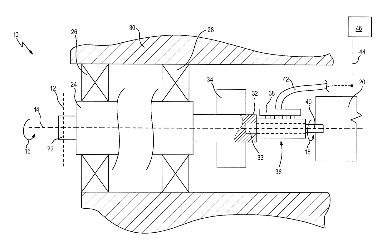
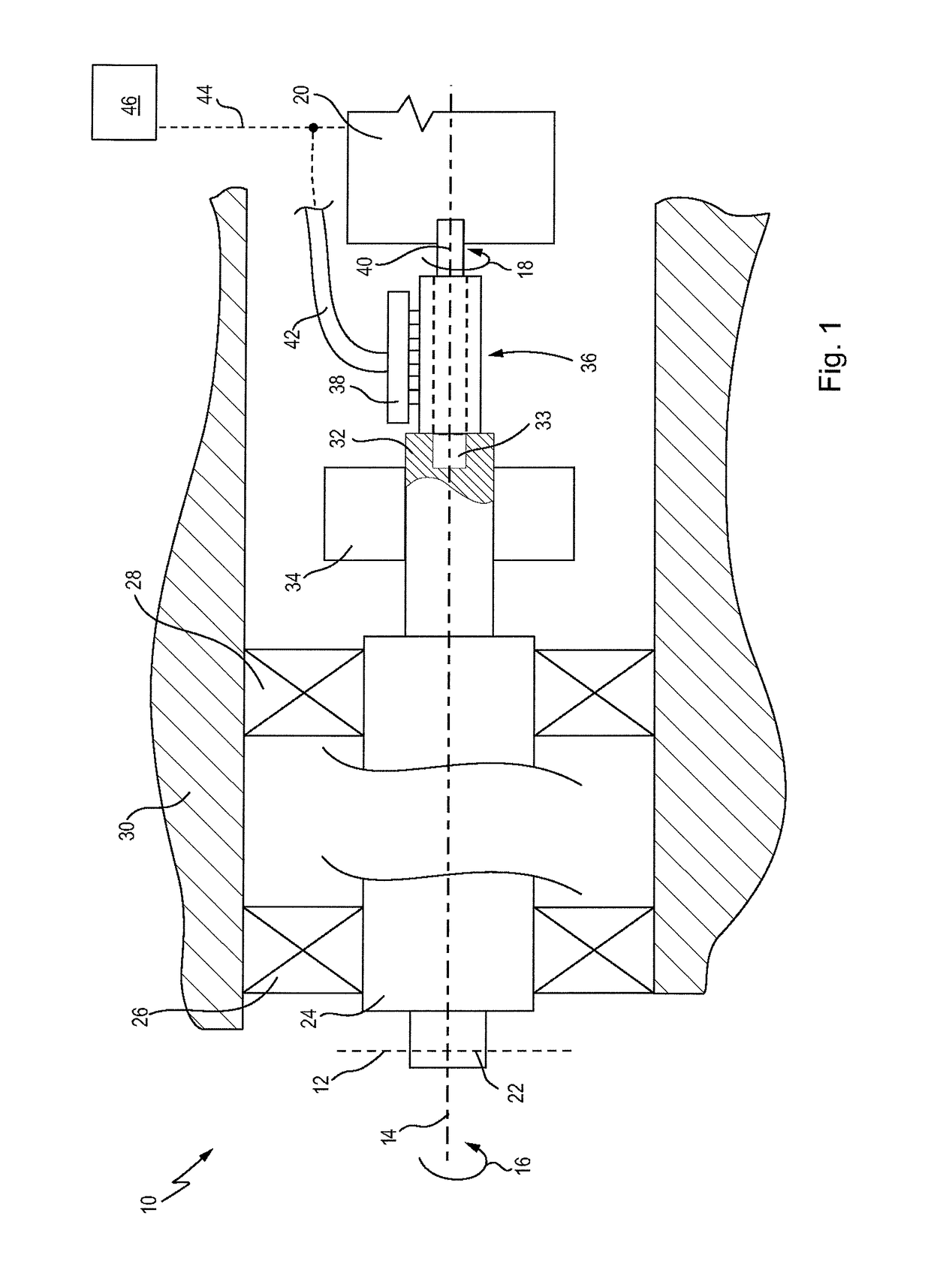
[0076]FIG. 1 shows an embodiment of a rotary coupling arrangement 10. A rotary coupling arrangement 10 of this kind can be used, in particular, in coordinate measuring devices. Said rotary coupling arrangement is used, for example, to couple a sensor to a support structure in a rotatable manner. In particular, it is possible to rotate freely through 360° several times, so-called n×360° rotatability. In this case, the dimensions of the rotary coupling arrangement can be freely selected. Furthermore, other applications are also feasible, for example in rotary tables or in other applications when rotation axes are intended to be freely pivoted through more than 360°. The use of the rotary coupling arrangement 10 in a coordinate measuring device, where it serves for coupling to a sensor, will be described in the text which follows.

[0077]To this end, the rotary coupling arrangement 10 has a sensor interface 12. A sensor can be arranged on the sensor interface 12, said sensor then being f...


PUM


Abstract

A rotor arrangement for a slip ring assembly, comprising a shaft element and at least one contact ring. The shaft element is at least partially in the form of a hollow shaft with a hollow interior and a casing wall. The shaft element has a middle section and each contact ring is arranged on the shaft element in the middle section and is electrically insulated from the shaft element by means of an insulation. The middle section has at least one cutout through the insulation and the casing wall into the interior. Each contact ring is connected to a cable element which is guided through one of the at least one cutout into the interior. The shaft element has a first end section with an outer circumferential cross section for the rotationally fixed coupling. Furthermore, a rotary coupling arrangement comprising a rotor arrangement of this kind is proposed.

Description

CROSS-REFERENCE TO RELATED APPLICATIONS[0001]This application is a continuation of International patent application PCT / EP / 2015 / 078699, filed Dec. 4, 2015, which claims priority of German patent application DE 10 2014 118 359.2, filed Dec. 10, 2014. The entire content of both applications is herewith incorporated by reference.BACKGROUND OF THE INVENTION[0002]The present invention relates to a rotor arrangement for a slip ring assembly. Furthermore, the present invention relates to a rotary coupling arrangement comprising a slip ring assembly.[0003]In the prior art, in particular in the field of coordinate measuring technology, it is customary to fit the sensors used to support structures which allow the sensors to move freely within a measurement area. The support structures are known in various forms, for example in the form of gantry constructions or else horizontal arm constructions. The support structures often have rotation axes which allow an arrangement, for example the senso...

Claims


Application Information

Patent Timeline
Patent Type & Authority Patents(United States)
IPC IPC(8): H01R13/639H01R39/34H01R39/14
CPCH01R39/14H01R39/34H01R39/64H01R43/10H01R2201/20
Inventor WOLETZ, TOBIASKAUFMANN, DIETER
Owner CARL ZEISS IND MESSTECHN GMBH
Why Eureka
Try Eureka