Dual-headed paint spray wand

a paint spraying wand and double-headed technology, applied in the direction of spraying apparatus, spray nozzle, liquid spraying apparatus, etc., can solve the problems of poor transfer efficiency, high efficiency of paint spraying systems, waste of as much as 60%,

Active Publication Date: 2018-11-13
COWAN MARK A
View PDF5 Cites 0 Cited by
  • Summary
  • Abstract
  • Description
  • Claims
  • Application Information

AI Technical Summary

Benefits of technology

[0004]The present invention is a dual-headed paint spray wand comprising a central paint feed tube that attaches at one end to a standard airless paint spray gun and attaches at the other end to a three-way manifold that splits the central feed tube into two arms, each with a 90° offset bend. At the end of each arm is a standard threaded coupling permitting the attachment to the end of each arm of a standard paint spray assembly comprising a tip guard, reversible paint spray tip and an on-off knob. The two arms are spaced apart so as to create an overlap of approximately 40% to 50% between the paint spray fans. The overlap is design to provide twice the coverage of traditional paint sprayers with each pass of the gun. In addition, the two arms are vertically offset. This is done to avoid having the spray fans collide and create turbulence.
[0005]In operation, a user of the invention attaches the wand to the paint feed tubing of any standard airless paint sprayer. The invention draws paint from the paint sprayer through the central feed tube, into the three-way manifold and into the two arms, where the paint flows into paint spray tips contained in two paint spray assemblies and out onto the surface to be painted in the shape of a fan. Because of the 40% to 50% overlap in the paint spray fans created by the spacing of the two arms, the invention permits the user to cover twice as much surface area as one using a sprayer equipped with only one tip, which effectively cuts labor time in half. Because of the vertical offset between tips, making one spray in advance of the other, the wand design avoids having the spray fans collide and create turbulence.

Problems solved by technology

The prior art for paint spray systems is, however, highly inefficient, relying as it does upon a single paint spray tip, which is often mounted on a single paint spray arm.
This results in poor transfer efficiency from overspray, often resulting in as much as 60% waste, and a slow application rate.

Method used


Image

  • Dual-headed paint spray wand
  • Dual-headed paint spray wand
  • Dual-headed paint spray wand

Examples


Embodiment Construction

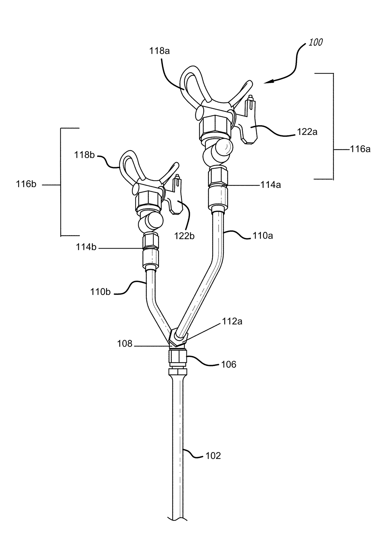
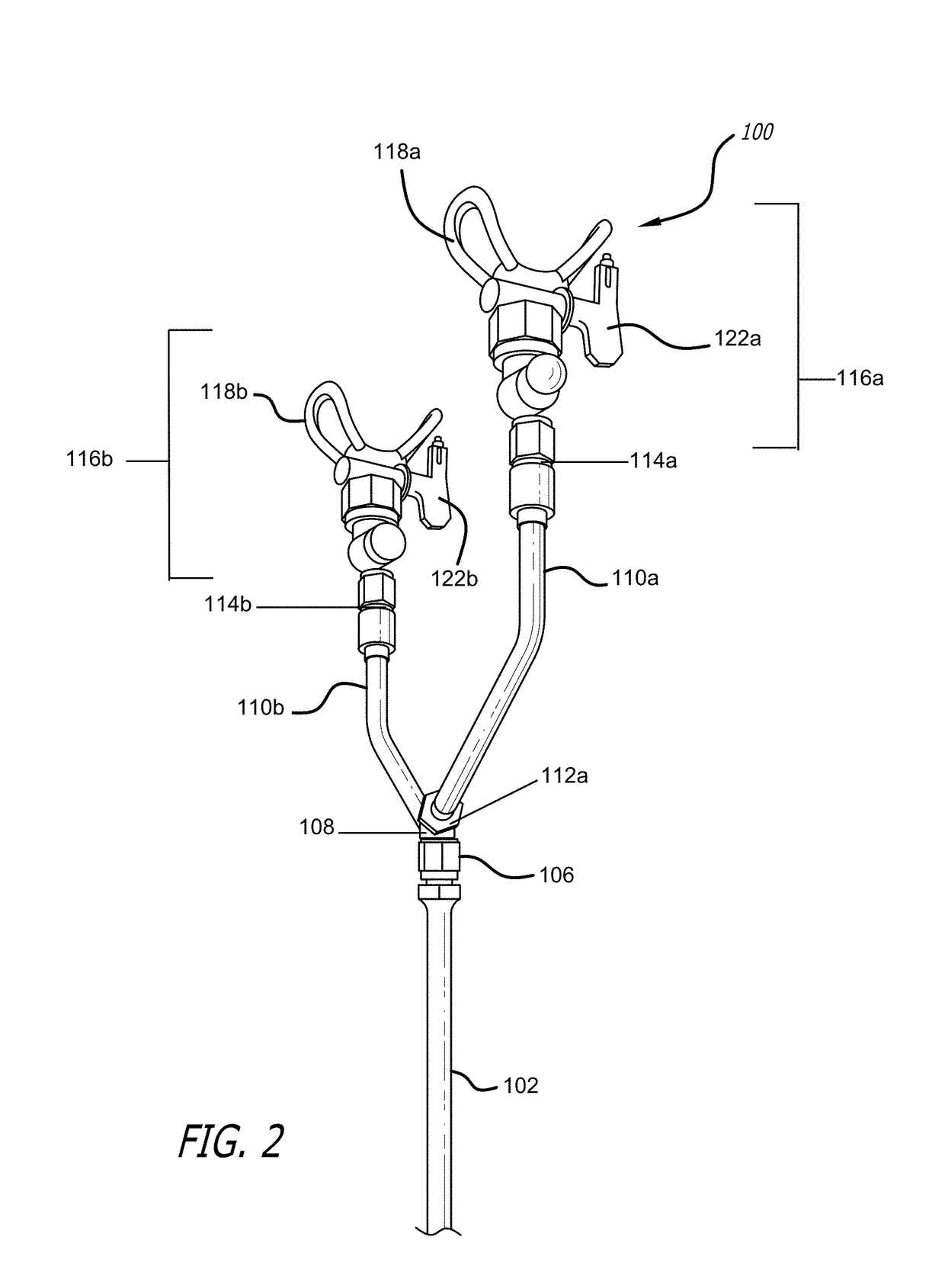
[0021]As illustrated in FIGS. 1-12, the present invention is a dual-headed paint spray wand 100. As will be explained further below, the dual-headed spray wand 100 of the present invention provides better coverage than traditional paint sprayers and cuts down on painting time.

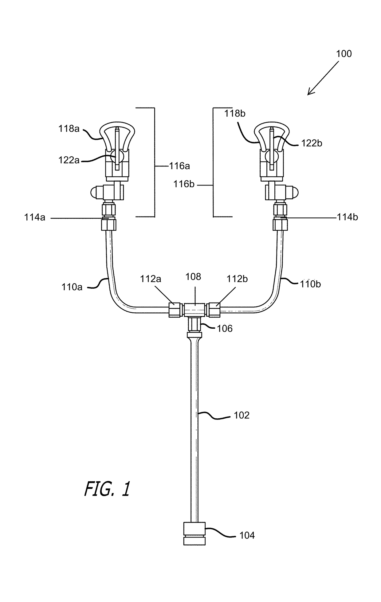
[0022]FIG. 1 is a front view of one example of an implementation of a paint spray wand 100 of the present invention. As illustrated by FIG. 1, the wand 100 consists of a central paint feed tube 102 between 2″ and 10″ in length that attaches at one end to a standard airless paint spray gun (not shown) using a hand-tightening or wrench tightened threaded connection 104. The feed tube 102 attached at the end opposing attachment to the paint spray gun to a three-way manifold 108 via threaded connection 106.

[0023]The three-way manifold 108 splits the central feed tube 102 into two arms 110a and 110b, positioned upward and separated from one other at a predetermined distance. As shown in FIG. 1, each arm may be conne...


PUM


Abstract

A dual-headed paint spray wand with a central feed tube split into two arms, where the arms are separated at a distance from one another to permit a paint overlap when paint is sprayed from the two arms, and where the two arms are offset from one another vertically to allow one arm to spray ahead of the other.

Description

RELATED APPLICATIONS[0001]This application claims priority of U.S. application Ser. No. 62 / 199,174, filed on Jul. 30, 2015, titled DUAL-HEADED PAINT SPRAY WAND, which application is incorporated in its entirety by reference in this application.FIELD OF THE INVENTION[0002]The invention relates to a dual-headed paint spray wand.BACKGROUND OF THE INVENTION[0003]Because the cost of both labor and material are two of the most important factors in the overall cost of a painting job, paint spray devices are often employed to control these costs. The prior art for paint spray systems is, however, highly inefficient, relying as it does upon a single paint spray tip, which is often mounted on a single paint spray arm. This results in poor transfer efficiency from overspray, often resulting in as much as 60% waste, and a slow application rate. A need thus exists for a paint spray system that offers greater efficiencies than existing systems in terms of both time and material savings.SUMMARY OF...

Claims


Application Information

Patent Timeline
Patent Type & Authority Patents(United States)
IPC IPC(8): B05B15/60B05B1/04
CPCB05B1/04B05B13/0278B05B15/60B05B9/0423
Inventor COWAN, MARK A.
Owner COWAN MARK A
Why Eureka
Try Eureka