Indented Tube for a Heat Exchanger

Active Publication Date: 2007-10-11
HANON SYST
View PDF12 Cites 1 Cited by
  • Summary
  • Abstract
  • Description
  • Claims
  • Application Information

AI Technical Summary

Benefits of technology

[0007] The tube includes indentations that increase the surface area of the tubes and the amount of fluid located proximate to the walls of the tubes. The indentations also create turbulence in the fluid flowing through the tubes.

Problems solved by technology

The indentations also create turbulence in the fluid flowing through the tubes.

Method used


Image

  • Indented Tube for a Heat Exchanger
  • Indented Tube for a Heat Exchanger
  • Indented Tube for a Heat Exchanger

Examples


Embodiment Construction

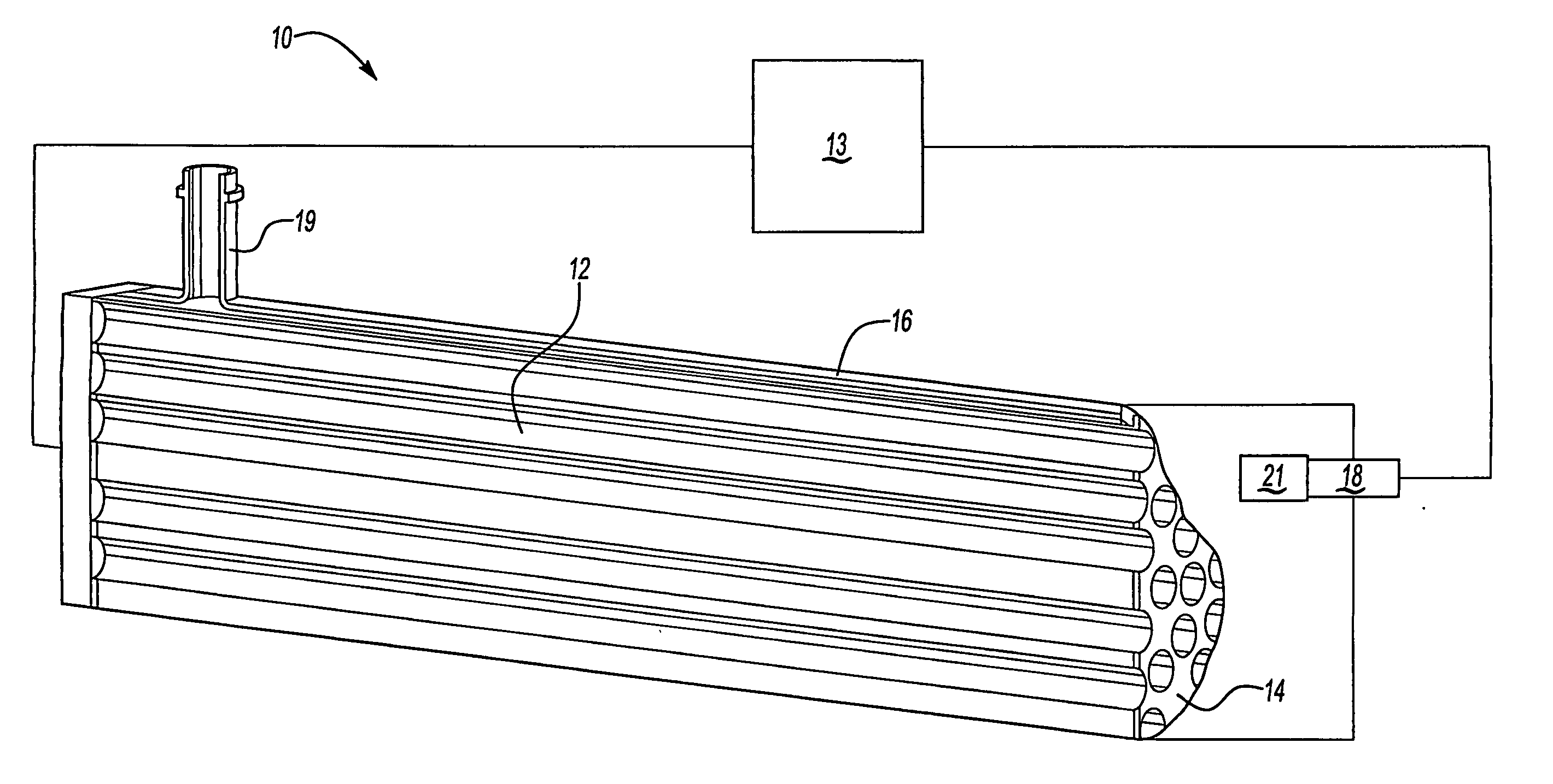
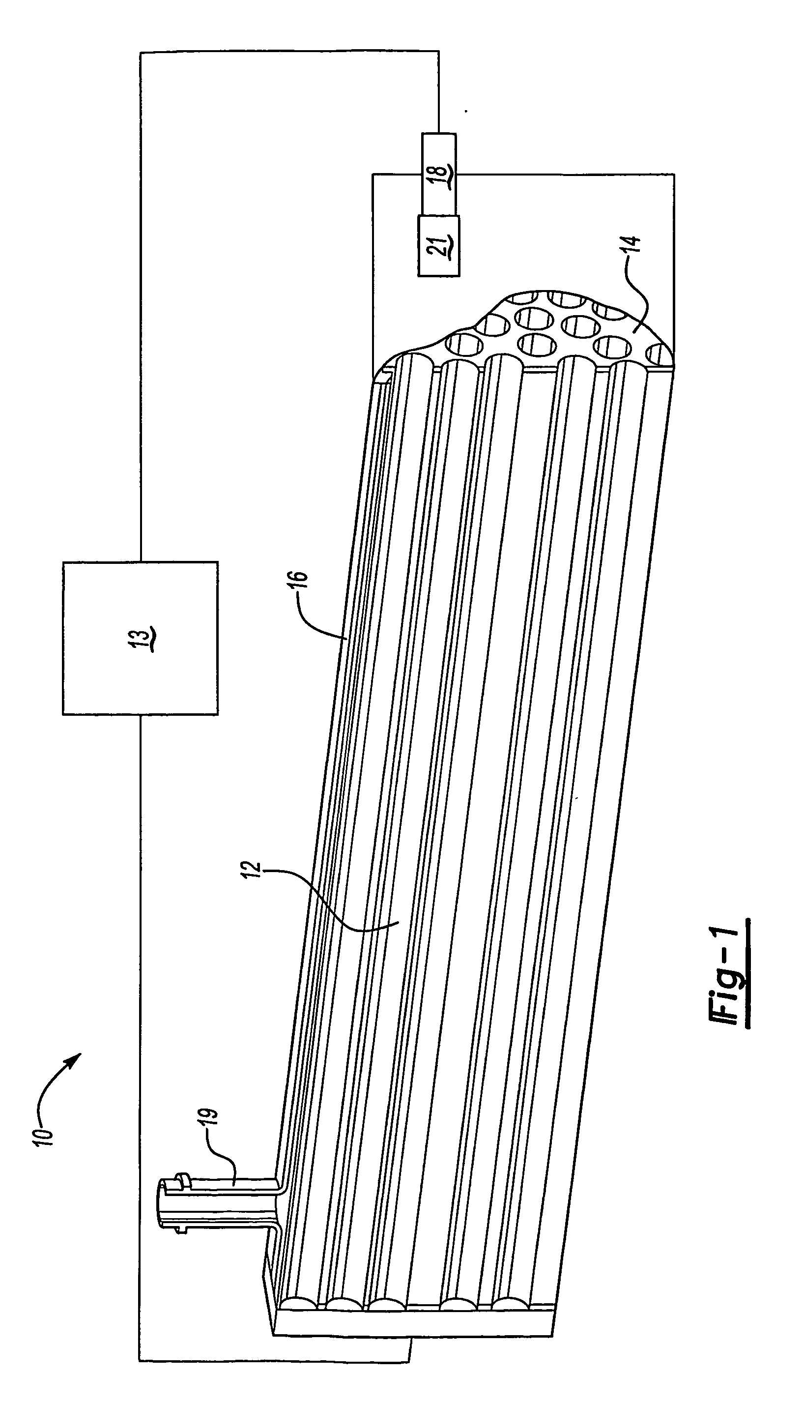
[0020]FIG. 1 illustrates a shell and tube heat exchanger 10 including a plurality of tubes 12 surrounded by a shell 16. Opposing end portions 26 of the tubes 12 are attached to a plate 14. The end portions 26 of the tubes 12 can be attached to the plate 14 by welding, press-fitting, or by any other means of attachment. A cooling fluid enters the heat exchanger 10 through an inlet 18 located at one end of the heat exchanger 10. The cooling fluid flows through the shell 16 and exchanges heat with a hot fluid that flows through the tubes 12. The fluid in the shell 16 exits the heat exchanger 10 through an outlet 19.

[0021] If the heat exchanger 10 is used with an exhaust gas recirculation system, an exhaust gas recirculation valve 21 controls the flow of hot fluid from an engine 13 or other component into the heat exchanger 10. If the heat exchanger 10 is used in an exhaust gas recirculation system, the hot fluid is an exhaust fluid. The hot exhaust fluid enters the tubes 12, and heat ...


PUM

PropertyMeasurementUnit
Angleaaaaaaaaaa
Flow rateaaaaaaaaaa

Abstract

A shell tube and heat exchanger (10) includes a plurality of tubes surrounded by a shell (16). Each tube (12) includes a plurality of indentations. A mold is placed in a desired positions and orientation in a die. A tube is placed in a first position within a die, and the mold crimps the tube to form the desired indentation in the tube. The mold is then released, and the tube is moved relative to the mold to a second position. The mold again crimps the tube to form an additional indentation. Alternately, the mold includes a roller that forms a groove on the tube. The tube is translated or both translated and rotated relative to the mold to form the groove.

Description

BACKGROUND OF THE INVENTION [0001] The present invention relates to a method for forming a tube used in a heat exchanger including a plurality of indentations that increase heat transfer between a fluid flowing through the tube and a fluid flowing around the tube. [0002] A shell and tube heat exchanger is used to cool fluids in various automotive applications, including exhaust gas recirculation coolers and power steering devices. In an engine gas recirculation system, an exhaust fluid flows inside the tube and exchanges heat with a coolant flowing around the tube. The exhaust fluid closer to the tube wall cools faster than the exhaust fluid flowing in the center of the tube. [0003] In the prior art, the tubes in the heat exchanger can be bent or twisted to create turbulence in the exhaust fluid and to provide a non-linear flow path to increase heat transfer. [0004] There are several drawbacks to the bent or twisted tubes of the prior art. For one, it is difficult to manufacture the...

Claims


Application Information

Patent Timeline
IPC IPC(8): B21D17/02B21C37/15B21C37/20B21D17/04F28D7/16F28F1/02F28F1/06F28F1/10F28F1/42
CPCB21C37/15B21C37/158B21C37/202B21D17/02B21D53/06F28F1/426F28D21/0003F28F1/006F28F1/025F28F1/06F28F1/42F28D7/16F28F2210/06
Inventor HOLDEN, JERRY L.
Owner HANON SYST
Why Eureka
Try Eureka