Moving-bed particle heat exchanger

Pending Publication Date: 2022-09-22
COMMONWEALTH SCI & IND RES ORG
View PDF0 Cites 0 Cited by
  • Summary
  • Abstract
  • Description
  • Claims
  • Application Information

AI Technical Summary

Problems solved by technology

The particle flow impacts the top of the tubes, and therefore creates cone-shaped stagnant zones at the top of the horizontal tubes and void zones below the horizontal tubes, significantly reducing the effective heat transfer area of the tubes.
In addition, the limitation in the size of the duct requires multiple manifolds/bends to connect the horizontal tube array for large-scale systems.
Due to size limitation of fabricating micro-chan

Method used


Image

  • Moving-bed particle heat exchanger
  • Moving-bed particle heat exchanger
  • Moving-bed particle heat exchanger

Examples


example 1

Heat Transfer Analysis—2D Heat Transfer Model

[0097]FIG. 6 shows a heat transfer model of a single tube-in-bed PHX which solves a two-dimensional steady-state conservation energy equation. The model was developed to understand particle-side heat transfer and provide a guide for conceptual design. For the condition of axial symmetry with respect to the tube centre axis, the tube-in-bed PHX can be assumed to be a 2D axisymmetric problem instead of a 3D problem. In this model, the particles are assumed to behave as a single continuous medium moving downwardly under gravity along the outer surface of the tube (heat transfer wall). The heat transfer between a moving particle bed and a heat transfer wall takes place by thermal conduction in the radial direction. It can be composed of two thermal resistances: a particle-wall contact resistance (Rnw) where heat transfer occurs between the first layer of particles (higher porosity region considering spherical particles in contact to the wall)...

example 2

Heat Transfer Analysis—Staged Moving-Bed 2D Heat Transfer Model

[0105]FIG. 11 shows a schematic diagram of a staged moving-bed particle heat exchanger connecting in series. In this example, the PHX is divided into a number of stages (Nstage) and assumed full mixing of particles at the outlet before entering to the next stage. In each stage, the heat transfer between a moving particle bed and a heat transfer wall is calculated using the methodology mentioned in Example 1 by solving a two-dimensional steady-state conservation energy equation.

[0106]FIG. 12 shows a comparison of bulk-to-wall heat transfer coefficient (hp) as a function of particle velocity (up) for a single stage PHX, 4 stages PHX and 10 stages PHX. The total heat exchanger length (Lhx) for all three cases is set to be 2 m. The results reveal that as the particle velocity (up) increases, a series of shorter PHXs comparing to a single stage PHX enables enhancement of the particle-side heat transfer coefficient through re-...

example 3

Experimental Works—Cold Flow Test Rig (Embodiment 1)

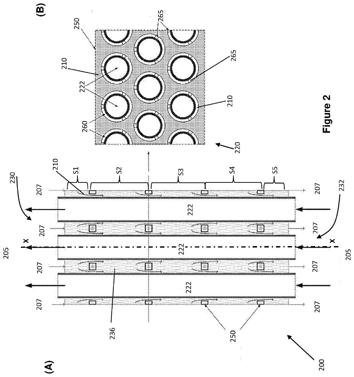
[0107]Experimental works were undertaken to investigate particles flow behaviour in a heat exchanger configuration shown in accordance with FIG. 2. As illustrated in FIG. 13, an experimental rig was constructed to study particle movement through the heat exchanger in room temperature conditions (i.e. not using heated particles). For the flow visualisation, the housing and dividers of the test rig were made from clear polycarbonate, which configured to enclose particles flow and a bundle of metal tubes.

[0108]The experimental rig was tested with particles (300 μm ceramic proppants comprising 75% Al2O3, 11% SiO2, 9% Fe2O3, and 3% TiO) packed in the housing and an upper bin. Particles are released from the heat exchanger by opening the slide gate at the bottom of the test rig.

[0109]The results of one run are illustrated in FIGS. 13B (A) to (D) which show the progress of the top of the particle flow through the cold flow experimental ri...


PUM


Abstract

A particle heat exchanger comprising: a housing including an inlet located at the top of the housing, and an outlet located below the inlet, the housing configured to enclose a flow of heat transfer particles which flows downwardly from the inlet to the outlet within the housing; at least one heat transfer tube enclosed in the housing and in contact with the flow of heat transfer particles therein, each heat transfer tube extending substantially parallel to an axis extending between the inlet and outlet of the housing; and at least one divider located between the inlet and outlet of the housing, the at least one heat transfer tube extending through each divider, each divider including at least one opening configured to form at least one flow constriction in the flow of heat transfer particles between the inlet and outlet of the housing.

Description

CROSS REFERENCE[0001]The present application claims priority from Australian provisional patent application No. 2019903064 filed on 22 Aug. 2019 the contents of which should be understood to be incorporated into this specification by this reference.TECHNICAL FIELD[0002]The present invention generally relates to a moving-bed particle heat exchanger configured to transfer heat between a moving bed of heat transfer particles and a heat transfer medium. The present invention is particularly applicable for transferring heat from heat transfer particles heated by solar energy from a solar receiver to a heat transfer medium and will be described in relation to that exemplary application. However, it should be appreciated that the moving-bed particle heat exchanger could be used in a wide variety of other heat exchange applications which involve heat transfer between particles and another heat transfer medium which could be either heat source or sink.BACKGROUND OF THE INVENTION[0003]The fol...

Claims


Application Information

Patent Timeline
IPC IPC(8): F28D13/00
CPCF28D13/00F28D20/0056F28D19/02F28C3/16F24S2080/011F28D2021/0045F28D2020/0069F28D2020/0086F28D7/16F24S60/00F24S80/20F24S90/00Y02E10/40
Inventor SOO TOO, YEN CHEANGARDNER, WILSONKIM, JIN-SOO
Owner COMMONWEALTH SCI & IND RES ORG
Why Eureka
Try Eureka