Pressure compensated glass unit

a technology of pressure compensation and glass unit, which is applied in the direction of parallel plane units, doors/windows, building components, etc., can solve the problems of desiccant being saturated or spent, glass panes, seals, etc., and achieve the effect of improving the properties of glass lite and improving the properties of film layer

Active Publication Date: 2018-11-13
LITEZONE TECH
View PDF46 Cites 2 Cited by
  • Summary
  • Abstract
  • Description
  • Claims
  • Application Information

AI Technical Summary

Benefits of technology

[0044]The pressure equalization conduit may end for any distance within the spacer. In some embodiments, the pressure equalization conduit may extend within the spacer less than once around the perimeter of the glass unit. In some embodiments, the pressure equalization conduit may extend within the spacer at least once around the perimeter of the glass unit. In some embodiments, the pressure equalization conduit may extend within the spacer more than once around the perimeter of the glass unit. In some embodiments, the pressure equalization conduit may extend within the spacer several times around the perimeter of the glass unit. In general, the performance and service life of the glass unit may increase / improve as the length of the pressure equalization conduit is increases.
[0054]The spacer may be constructed of any suitable material or combination of materials. In some embodiments, the spacer may be comprised of one or more materials which have reasonably good thermal insulating properties. In some embodiments, the spacer may be comprised of one or more materials which are reasonably resilient, flexible, and / or strong. In some embodiments, the spacer may be comprised of one or more materials which have a coefficient of expansion which is generally comparable to the coefficient of expansion of the front glass plane and the back glass pane, in order to avoid excessive differential expansion and contraction between the spacer and the glass panes.
[0063]In some embodiments, the length of the pressure equalization conduit between the first end port and the second end port may be maximized in order to maximize the distance a fluid must travel within the pressure equalization conduit to transfer between the exterior of the glass unit and the interior space of the glass unit.
[0068]In some embodiments, the glass unit may be comprised of one or more spacer seals around the perimeter of the glass unit for providing a seal between spacer members. In embodiments in which one or more of the spacer members are unitary spacer members, the need for spacer seals may be reduced or eliminated.
[0077]In embodiments of the glass unit which are comprised of one or more intermediate layers, the glass unit may be comprised of one or more floating suspension systems, wherein the perimeters of the intermediate layers are supported by the spacer with the floating suspension systems. In some embodiments, the floating suspension systems may support the intermediate layers within the interior space of the glass unit so that the intermediate layers are in a spaced-apart parallel relationship with the front glass pane and the back glass pane. In some embodiments, the floating suspension systems may support the intermediate layers within the interior space of the glass unit so that the intermediate layers are capable of moving biaxially within the interior space of the glass unit.

Problems solved by technology

Unfortunately, the components of a sealed glass unit (such as the glass panes, intermediate layers, and seals) can be exposed to significant stresses due to temperature and pressure fluctuations which may occur within the interior space of the glass unit during the installation life of the glass unit.
A disadvantage of using a desiccant in a glass unit is that the desiccant becomes saturated or spent as it absorbs and / or adsorbs moisture.

Method used


Image

  • Pressure compensated glass unit
  • Pressure compensated glass unit
  • Pressure compensated glass unit

Examples


Embodiment Construction

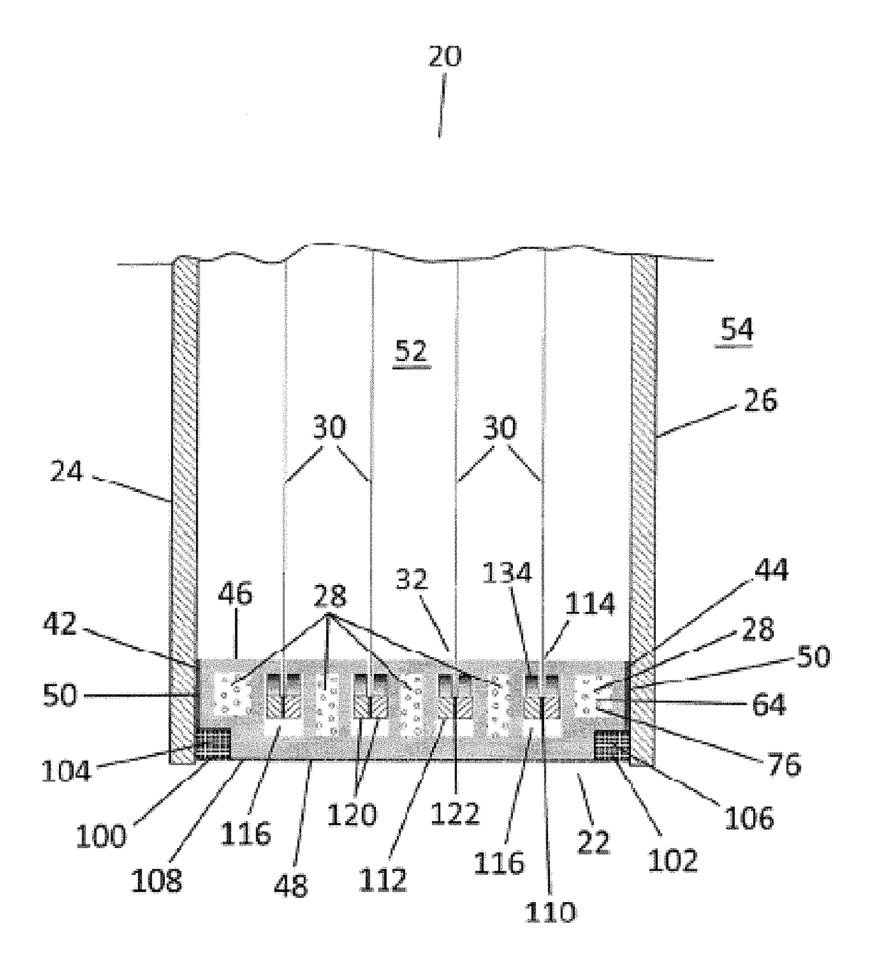
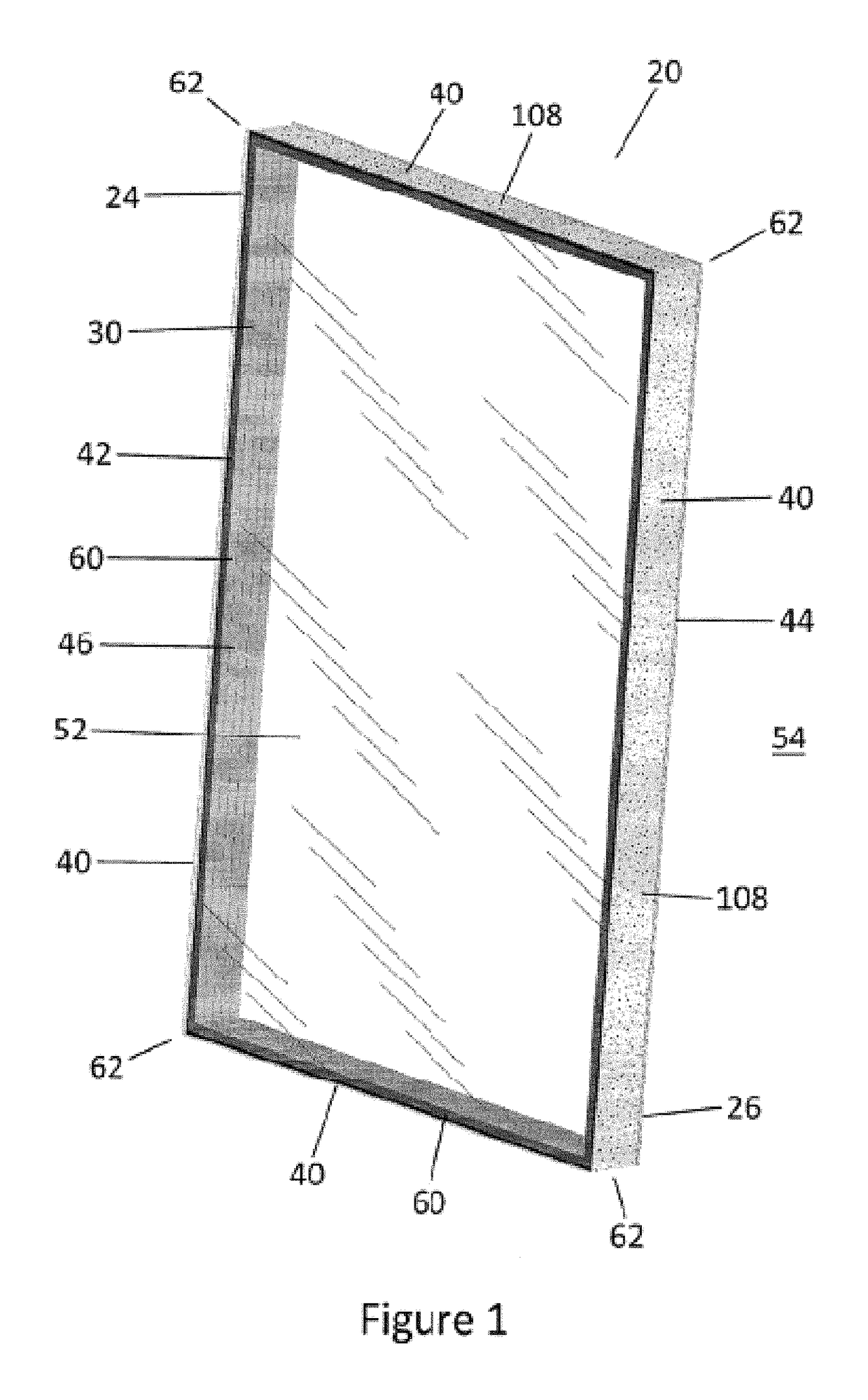
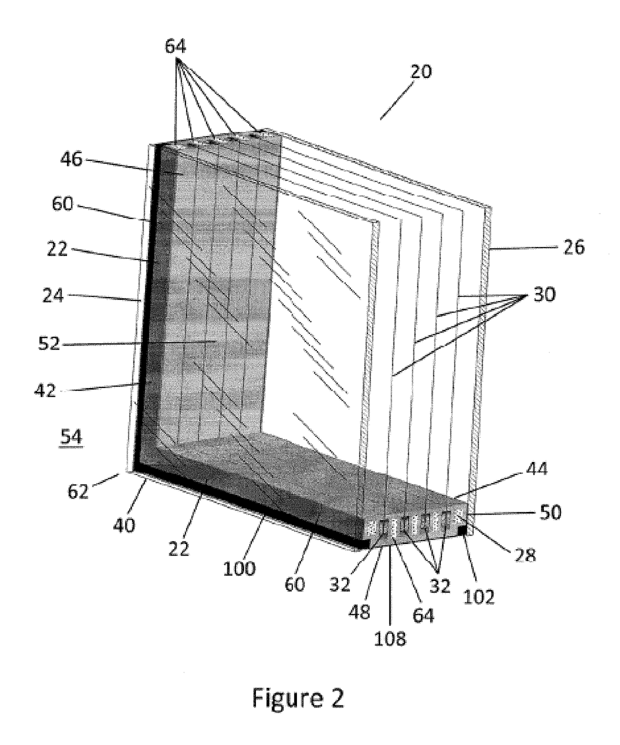
[0131]The present invention is directed at a pressure compensated glass unit.

[0132]Two exemplary embodiments of the glass unit are depicted in FIGS. 1-18. FIGS. 1-15 depict a first exemplary embodiment of the glass unit in which the glass unit comprises a plurality of intermediate film layers. FIGS. 16-18 depict a second exemplary embodiment of the glass unit in which the glass unit comprises a plurality of intermediate glass lites.

[0133]FIGS. 7-15 depict details of an exemplary embodiment of a pressure equalization conduit which is included in the first exemplary embodiment of the glass unit of FIGS. 1-15. The pressure equalization conduit which is included in the second exemplary embodiment of the glass unit of FIGS. 16-18 is very similar to the exemplary embodiment of the pressure equalization conduit which is depicted in FIGS. 7-15.

[0134]In the description which follows, features of the second exemplary embodiment of the glass unit which are equivalent to features of the first e...


PUM


Abstract

A glass unit including a spacer, a front glass pane attached to a front side of the spacer, a back glass pane attached to a back side of the spacer, and a pressure equalization conduit defined by and within the spacer, wherein the pressure equalization conduit has a first end and a second end, wherein the pressure equalization conduit contains a desiccant and is in fluid communication with an exterior of the glass unit at a first end port adjacent to the first end and with an interior space of the glass unit at a second end port adjacent to the second end. The glass unit may further include one or more intermediate layers contained within the interior space and one or more floating suspension systems for supporting the intermediate layers.

Description

TECHNICAL FIELD[0001]A pressure compensated glass unit which includes a desiccant for providing relatively dry air within the interior space of the glass unit and which is scalable to provide a desired amount of thermal resistance of the glass unit.BACKGROUND OF THE INVENTION[0002]A complete window typically includes a glass unit and a window frame.[0003]A glass unit typically includes a pair of glass panes and a spacer, wherein the pair of glass panes is separated and held in a spaced-apart parallel relationship by the spacer, thereby defining an interior space within the glass unit.[0004]A glass unit may also include one or more intermediate layers within the interior space, between the pair of glass panes. The intermediate layers may be constructed of film, glass or some other suitable material. A purpose of the intermediate layers is to increase the thermal resistance of the glass unit. The thermal resistance of a glass unit generally increases with a number of intermediate laye...

Claims


Application Information

Patent Timeline
Patent Type & Authority Patents(United States)
IPC IPC(8): E06B3/677E06B3/663E06B7/02E06B7/12E06B7/14E06B3/67
CPCE06B3/677E06B3/66347E06B3/66361E06B3/66366E06B7/02E06B7/12E06B7/14E06B3/6715E06B2003/66395E06B2003/6638E06B3/66352E06B3/667
Inventor CLARAHAN, GREGORY L.
Owner LITEZONE TECH
Why Eureka
Try Eureka