Visual odometry for low illumination conditions using fixed light sources

a fixed light source and low illumination technology, applied in the field of performing visual odometry in low illumination conditions, can solve problems such as system failure, system error in estimating the state of objects, and typical feature locations such as those associated with corner points

Active Publication Date: 2018-11-13
HERE GLOBAL BV
View PDF15 Cites 10 Cited by
  • Summary
  • Abstract
  • Description
  • Claims
  • Application Information

AI Technical Summary

Problems solved by technology

Typical feature locations, such as those associated with corner points, are unstable across changes in scale, and orientation.
As a result, the lack of texture and discernable features in the imagery captured in low illumination conditions, such as at dusk and during the night, may cause the system to incorrectly estimate the state of the object.
The lack of ambient illumination causes traditional visual odometry systems to fail due to insufficient discernible features and / or texture to effectively perform the matching of features between images and the local optimization.

Method used


Image

  • Visual odometry for low illumination conditions using fixed light sources
  • Visual odometry for low illumination conditions using fixed light sources
  • Visual odometry for low illumination conditions using fixed light sources

Examples


Embodiment Construction

[0022]Some embodiments will now be described more fully hereinafter with reference to the accompanying drawings, in which some, but not all, embodiments of the invention are shown. Indeed, various embodiments of the invention may be embodied in many different forms and should not be construed as limited to the embodiments set forth herein; rather, these embodiments are provided so that this disclosure will satisfy applicable legal requirements. Like reference numerals refer to like elements throughout. As used herein, the terms “data,”“content,”“information,” and similar terms may be used interchangeably to refer to data capable of being transmitted, received and / or stored in accordance with embodiments of the present invention. Thus, use of any such terms should not be taken to limit the spirit and scope of embodiments of the present invention.

[0023]Additionally, as used herein, the term ‘circuitry’ refers to (a) hardware-only circuit implementations (e.g., implementations in analo...


PUM


Abstract

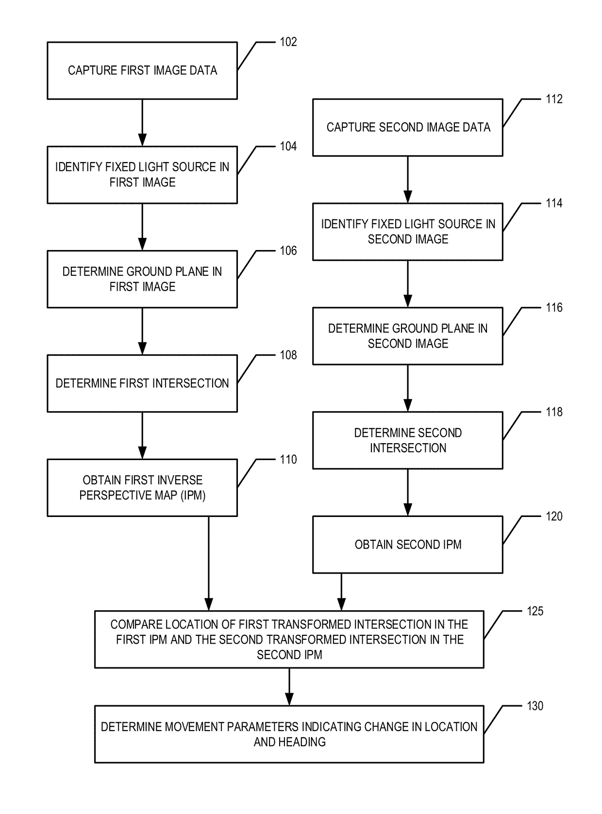
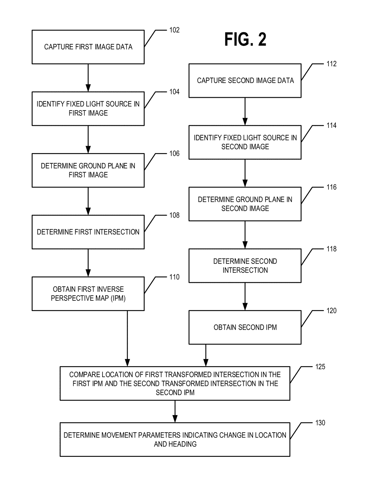
First and second image data is captured comprising a first and second image, respectively. A fixed light source is identified in each of the first and second images. A first ground plane is determined in the first image data. A first (second) intersection is determined, wherein the first (second) intersection is a point in the first image where a virtual lamp post corresponding to the fixed light source in the first (second) image intersects with the first (second) ground plane. The first image data and the second image data are transformed to provide a first and second inverse perspective map (IPM) comprising a first transformed intersection and a second transformed intersection, respectively. Movement parameters are determined based on the location of the first transformed intersection in the first IPM and the location of the second transformed intersection in the second IPM.

Description

TECHNOLOGICAL FIELD[0001]Example embodiments relate generally to performing visual odometry in low illumination conditions. In particular, example embodiments generally relate to performing visual odometry in low illumination conditions to monitor movement of an object, such as a vehicle, in real-time or near real-time.BACKGROUND[0002]Visual odometry is the process of incrementally estimating the current state of an object (defined as position and heading) using only camera images. Typical monocular visual odometry comprises feature extraction, feature matching between images, motion estimation, and local optimization. The features, typically extracted at corner points (e.g., corners of buildings and / or the like), are used to establish the correspondence between two temporally spaced monocular images. A feature matching framework is employed to filter out incorrect correspondences and return a list of pixel-wise matches. The motion estimation step uses the pairwise matches and the c...

Claims


Application Information

Patent Timeline
Patent Type & Authority Patents(United States)
IPC IPC(8): G06T7/00G06K9/00G06T7/20H04N5/225G06T7/246G06T7/269
CPCG06T7/70G06K9/00798G06T7/20G06T7/246H04N5/2256G06T7/269G06T2207/30256G06T2207/10016G06T2207/10024G06T2207/30244G06V20/588H04N23/56
Inventor VISWANATHAN, ANIRUDH
Owner HERE GLOBAL BV
Why Eureka
Try Eureka