Fuel cell manufacturing method and fuel cell manufacturing device

a manufacturing device and fuel cell technology, applied in the direction of final product manufacturing, sustainable manufacturing/processing, electric/magnetic/electromagnetic heating, etc., can solve the problem of deteriorating power generation performance of the fuel cell

Inactive Publication Date: 2018-11-13
NISSAN MOTOR CO LTD
View PDF11 Cites 0 Cited by
  • Summary
  • Abstract
  • Description
  • Claims
  • Application Information

AI Technical Summary

Benefits of technology

[0011]In the present invention, since induction current is selectively generated in a site to be heated by causing electric current to flow through coils, which are disposed on both sides of the site to be heated in the stacking direction, in the same direction as directions intersecting the stacking direction, it is possible to heat the site to be heated in a localized manner.

Problems solved by technology

If this location is heated to a high temperature, there is the risk that the power generation performance of the fuel cell deteriorates, which is undesirable.

Method used


Image

  • Fuel cell manufacturing method and fuel cell manufacturing device
  • Fuel cell manufacturing method and fuel cell manufacturing device
  • Fuel cell manufacturing method and fuel cell manufacturing device

Examples


Embodiment Construction

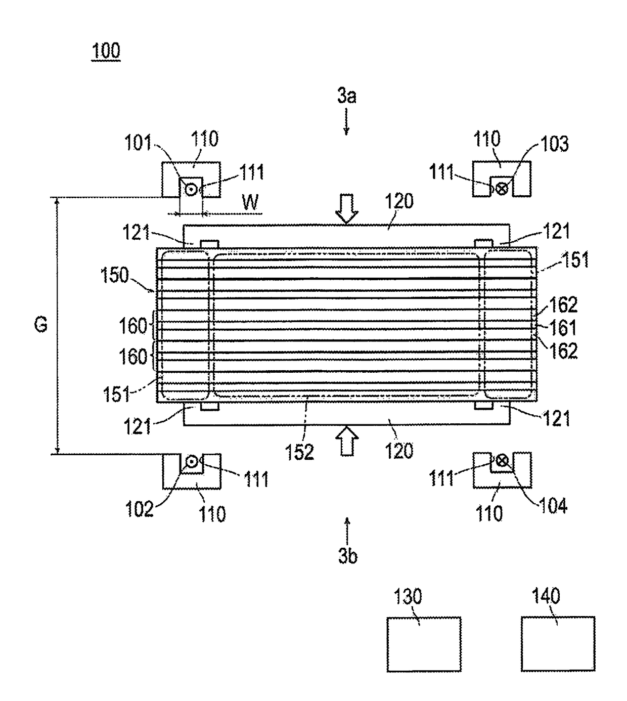
[0024]Embodiments of the present invention will be described below, with reference to the drawings. The dimensional ratios in the drawings are exaggerated for the sake of convenience of the explanation, and are different from the actual ratios.

[0025]The fuel cell manufacturing device 100 of the present embodiment comprises coils 101, 102, 103, 104, a plurality of magnetic path forming members 110, a pair of shielding members 120 (pressing fixture), a power source 130 and a control device 140, as illustrated in FIG. 1.

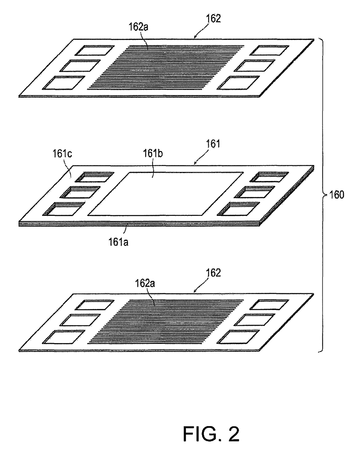
[0026]The coils 101, 102 are disposed on both sides of one of a pair of sites 151 to be heated of the fuel-cell module 150 (laminate) in the stacking direction of a membrane electrode assembly 161 and a pair of separators 162. The coils 101, 102 extend in the same direction as the direction that is perpendicular to the stacking direction of the membrane electrode assembly 161 and the separators 162 (the direction perpendicular to the figure in FIG. 1).

[0027]The coils 10...


PUM

PropertyMeasurementUnit
electricaaaaaaaaaa
electric currentaaaaaaaaaa
magnetic fluxaaaaaaaaaa

Abstract

A fuel cell manufacturing method and a fuel cell manufacturing device are provided in which it is possible to heat, in a localized manner, sections for which heating is desired. In this fuel cell manufacturing method, a laminate is obtained by stacking a membrane electrode assembly and a separator that has an adhesive disposed therebetween. Coils are provided adjacent a site of the laminate to be heated. Preferably, coils are disposed on opposite sides of the site in the stacking direction of the membrane electrode assembly and the separator such that current flows in the same direction as directions intersecting the stacking direction. The site to be heated is subjected to induction heating by passing current through the coils.

Description

[0001]This application is a U.S. National stage application of International Application No. PCT / JP2015 / 064536, filed May 20, 2015, which claims priority to International Application No. PCT / JP2014 / 063503 filed on May 21, 2014, the contents of which are hereby incorporated herein by reference.BACKGROUNDField of the Invention[0002]The present invention relates to a manufacturing method of a fuel cell and a manufacturing device of a fuel cell.Background Information[0003]A technique to cure an adhesive that is disposed between members that configure a fuel cell by induction heating is known. For example, in the invention disclosed in Japanese Laid Open Patent Application No. 2006-302741 (Patent Document 1), a laminate obtained by stacking a multiplicity of membrane electrode assemblies (MEA) and separators is subjected to induction heating to cure an adhesive disposed on the outer perimeter part thereof.[0004]Since a member is directly heated by induction heating, the heating time can ...

Claims


Application Information

Patent Timeline
Patent Type & Authority Patents(United States)
IPC IPC(8): H01M8/241B32B37/12H05B6/10H01M8/0286H05B6/36B32B7/14B32B37/00B32B37/06H01M8/1004
CPCH01M8/241B32B37/0076B32B37/065B32B37/1207B32B37/1292H01M8/0286H01M8/1004H05B6/10H05B6/365B32B7/14Y02P70/56B32B2037/1253B32B2250/03B32B2305/72B32B2307/202B32B2307/206B32B2309/022B32B2457/18Y02P70/50Y02E60/50H01M8/2404
Inventor ICHIHARA, KEIJITORII, NAOYUKISAITO, TSUNEOFUJII, TAKAHIKONAKATOMI, TERUHITO
Owner NISSAN MOTOR CO LTD
Why Eureka
Try Eureka