Three-dimensional ceramic heater

a ceramic heater and three-dimensional technology, applied in the direction of heater elements, vacuum evaporation coatings, coatings, etc., can solve the problem of short working life and achieve the effect of reducing localized extra heating

Active Publication Date: 2018-09-18
SHIN ETSU CHEM CO LTD
View PDF4 Cites 0 Cited by
  • Summary
  • Abstract
  • Description
  • Claims
  • Application Information

AI Technical Summary

Benefits of technology

[0033]According to the present invention, it is possible to mitigate the localized extra heating at the folded-back sections of the heater pattern, and also to prevent any divided electric current lane from being heated to outstandingly higher temperature than other lanes for the irregularity in the temperature to which each divided electric current lane is heated is suppressed, so that it is possible to provide a three-dimensional ceramic heater made of PG / PBN which has a long life in the service of heating the raw material-holding crucible in a vacuum deposition apparatus.BRIEF EXPLANATION OF THE DRAWINGS
[0034]FIG. 1 is an unfolded view of a heater pattern of a ceramic heater according to an embodiment of the present invention.
[0035]FIG. 2 is an enlarged view of a folded-back section of a heater pattern of a ceramic heater of the present invention, showing electric current lanes.
[0036]FIG. 3 is an unfolded view of a heater pattern of a ceramic heater according to another embodiment of the present invention.
[0037]FIG. 4 is an unfolded view of a heater pattern of a ceramic heater according to a still another embodiment of the present invention, which is described in Example 2 hereunder.
[0038]FIG. 5 is a schematic drawing to explain about the electric power density in the respective divided electric current lanes.

Problems solved by technology

However, a three-dimensional PG / PBN ceramic heater made in a manner such as these has a problem that the working life tends to be short when used to heat a raw material-holding crucible in a vacuum deposition apparatus wherein the heating temperature is as high as a thousand and several hundred degrees centigrade, and hence we will explain about this problem in detail using drawings.

Method used


Image

  • Three-dimensional ceramic heater
  • Three-dimensional ceramic heater
  • Three-dimensional ceramic heater

Examples


example 1 (

Not Claimed)

[0070]In Example 1, a pyrolytic boron nitride circular plate measuring 140 mm in diameter and 1 mm in thickness was made by reacting 4 slm (standard liter per minute) of ammonia with 2 slm of boron trichloride at a pressure of 10 Torr and a temperature of 1900 degrees centigrade. Next, a pyrolytic graphite layer of 50-micrometer thickness was formed on the circular plate by thermally cracking methane at a pressure of 5 Torr and a temperature of 1750 degrees centigrade; this layer was machine-cut into a heater pattern consisting of 8-mm-wide passages of heater element arranged to meander in the radial direction. As is seen in FIG. 9 (a), a pair of folded-back sections formed in the heater pattern are each divided—from a position E, at which the two folded-back sections face each other, through to a position 30 mm away from the position E—into two 4-mm-wide electric current lanes 18 and 19, the lane 18 being the inner lane at the folded-back section and the lane 19 being t...

example 2

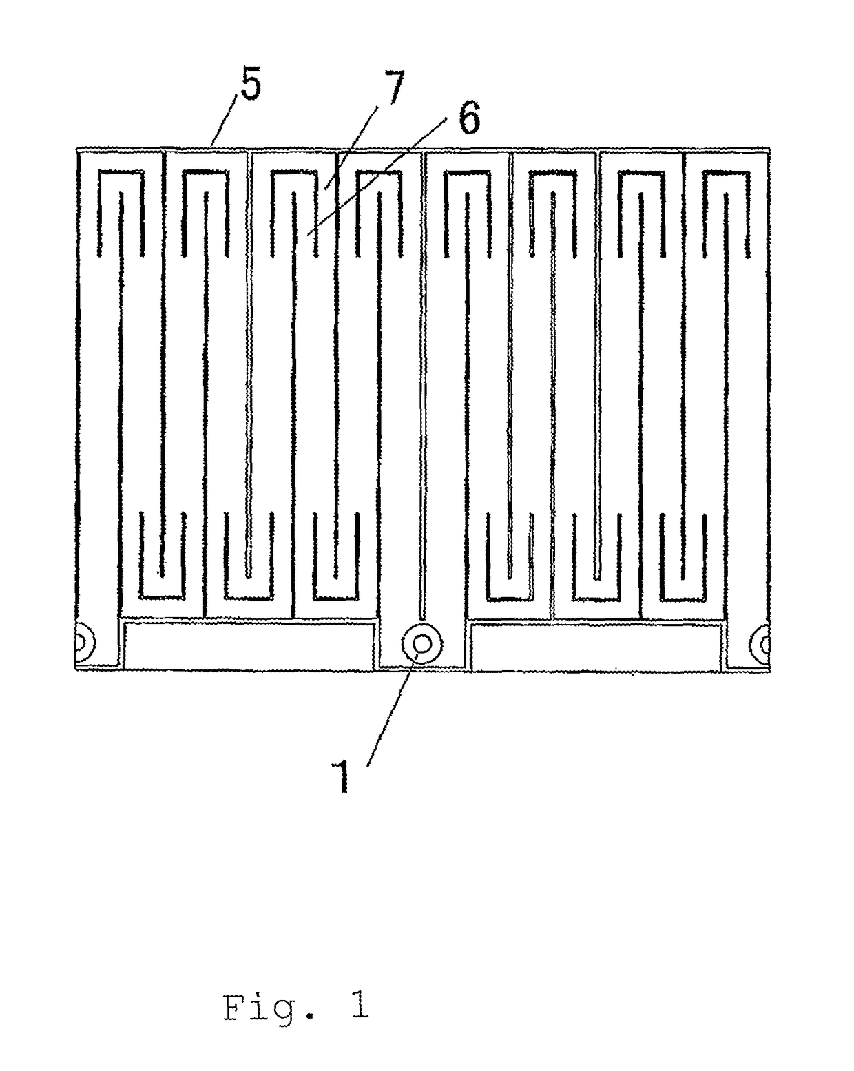
[0075]In Example 2, a pyrolytic boron nitride circular cylinder measuring 85 mm in outer diameter, 200 mm in height and 1.3 mm in thickness was made by reacting 4 slm of ammonia with 2 slm of boron trichloride at a pressure of 10 Torr and a temperature of 1900 degrees centigrade. Next, a pyrolytic graphite layer of 40-micrometer thickness was formed on the circular cylinder by thermally cracking methane at a pressure of 5 Torr and a temperature of 1750 degrees centigrade; this layer was machine-cut into a heater pattern as shown in FIG. 4. In this heater pattern the passage between the two electric power supply terminals 1, including the passage section between a folded-back section 14 and the closest electric power supply terminal and the passage section between the folded-back section 15 and the closest electric power supply terminal, was divided into an electric current lane 16 and an electric current lane 17, which extended continuously in parallel with the direction of the curr...


PUM

PropertyMeasurementUnit
temperatureaaaaaaaaaa
diameteraaaaaaaaaa
temperatureaaaaaaaaaa

Abstract

A three-dimensional ceramic heater, such as a cylindrical ceramic heater, is proposed in which the conductive ceramic heating element is multi-furcated into lanes at least in the folded-back sections so that the electric current tends to flow in a more uniform and hence laminar manner with the effect that the localized over heating is suppressed greatly.

Description

PRIORITY CLAIMED[0001]The present non-provisional application claims priority, as per Paris Convention, from Japanese Patent Application No. 2013-170963 filed on Aug. 21, 2013, the disclosure of which is incorporated by reference herein in its entirety.FIELD OF THE TECHNOLOGY[0002]The present invention relates to a three-dimensional ceramic heater used for heating a crucible holding a raw material in a vacuum deposition apparatus used for manufacturing of semiconductor, solar cell, organic EL display, etc.BACKGROUND TECHNOLOGY[0003]Vacuum deposition method is known as one of the procedures for forming a thin film, and this vacuum deposition method consists of steps of placing raw material(s) for deposition in a crucible, heating the crucible to a temperature above the vaporization point of the deposition material in the vacuum deposition apparatus to thereby create the vapor of the deposition material, and depositing the substance on a substrate to thereby form a thin layer. As a me...

Claims


Application Information

Patent Timeline
Patent Type & Authority Patents(United States)
IPC IPC(8): H05B3/08H05B3/26C23C14/26H05B3/48C23C14/14C23C14/24H05B3/14
CPCC23C14/14C23C14/243H05B3/141H05B3/48H05B3/265C23C14/26H05B2203/002
Inventor KUSHIHASHI, TAKUMAKIMURA, NOBORUTAMURA, KAZUYOSHI
Owner SHIN ETSU CHEM CO LTD
Why Eureka
Try Eureka