Transfer material, printed material, manufacturing apparatus for printed material, and manufacturing method for printed material

a technology of printing apparatus and printing material, which is applied in the direction of thermography, duplicating/marking methods, coatings, etc., can solve the problems of inability to adhere to the ink receiving layer, inability to adhere properly, so as to eliminate the need for primers, print resolution, and the effect of not deteriorating the printing characteristics of image bleeding

Active Publication Date: 2018-11-20
COPYER
View PDF31 Cites 3 Cited by
  • Summary
  • Abstract
  • Description
  • Claims
  • Application Information

AI Technical Summary

Benefits of technology

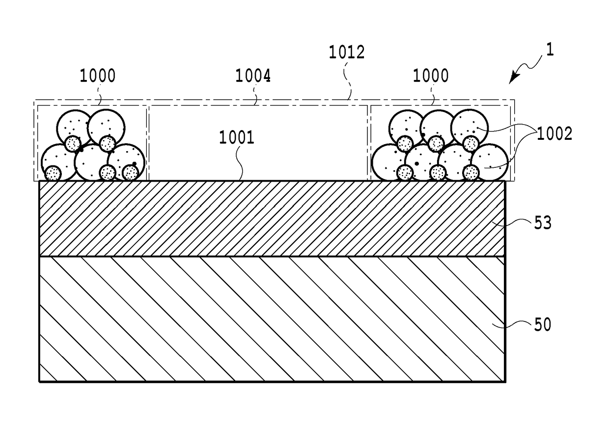
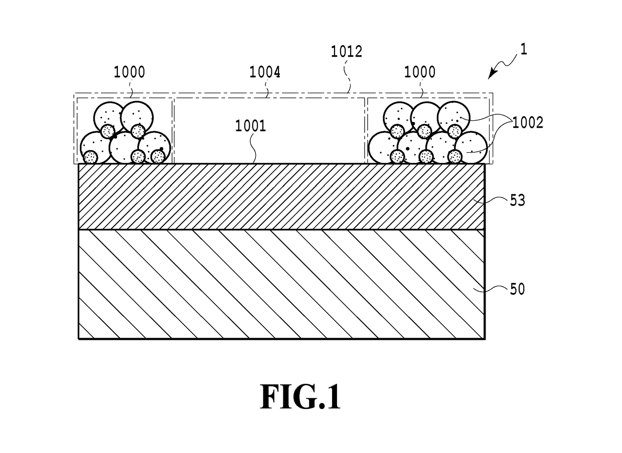
[0021]The present invention provides a transfer material that can be more firmly attached to an image substrate without deteriorating printing characteristics concerning image bleeding, printing resolution, and the like. The present invention allows an ink receiving layer to adhere to an image substrate after ink jet printing without limitation of a material for the image substrate, and eliminates the need for a primer.
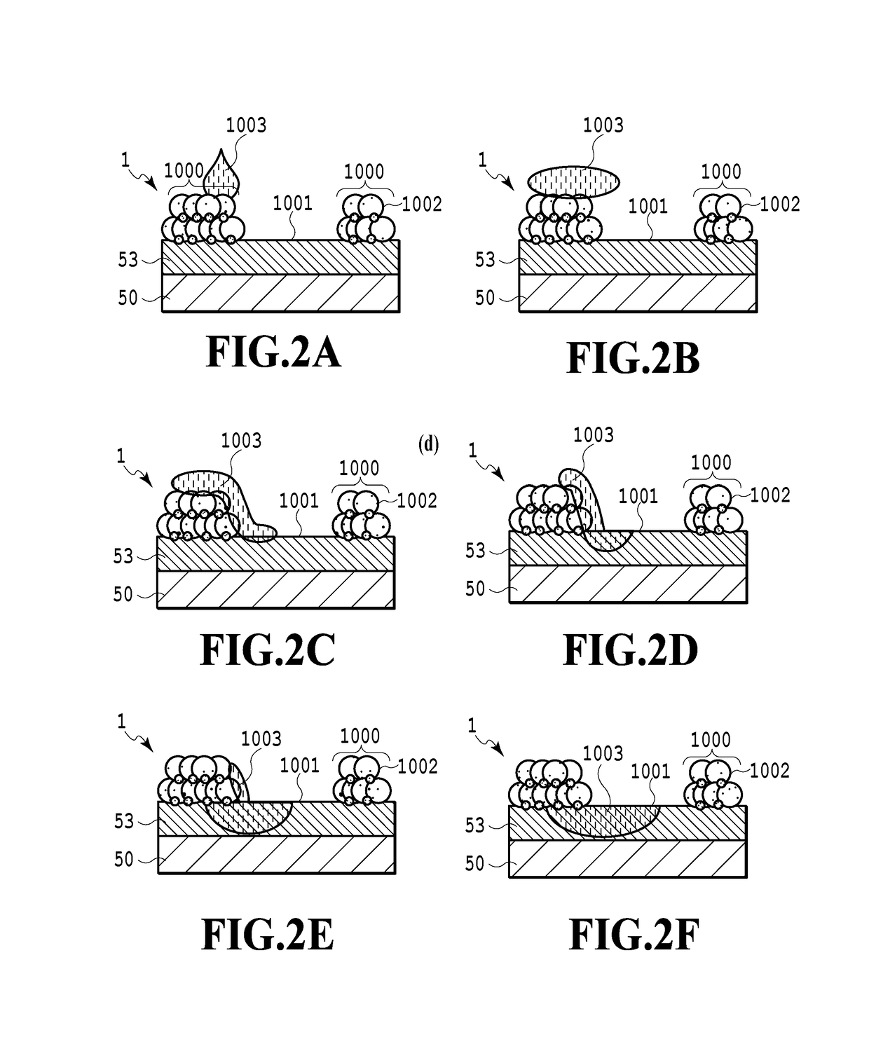
[0022]The transfer material in the present invention is configured to make color materials unlikely to remain on a surface of an adhesive and to quickly absorb ink into the ink receiving layer. To achieve this, an ink absorption speed of the ink receiving layer is set higher than an ink absorption speed of the adhesive to enable the ink on the adhesive surface to be quickly dragged and absorbed into the ink receiving layer.
[0023]That is, when a portion of the ink comes into contact with the surface of the ink receiving layer, which absorbs the ink at a higher absorption speed than the adhesive, the ink present on the surface of the adhesive or inside the adhesive can be quickly dragged into the ink receiving layer. The ink absorbed through the surface of the ink receiving layer sequentially infiltrates into the ink receiving layer, and is absorbed while spreading in a film thickness direction and a horizontal direction in accordance with permeability anisotropy of the ink receiving layer. The ink receiving layer is designed and produced to have such permeability anisotropy as enables appropriate control of spread of ink dots that are the basis of ink jet printing images. That is, when large ink dots are needed, the permeability in the horizontal direction is set higher than the permeability in the film thickness direction. In contrast, when small ink dots are needed and the amount of ink that can be absorbed is to be increased, the permeability in the film thickness direction may be set higher than the permeability in the horizontal direction, and the ink receiving layer may be made thick. To allow isotropic permeation to occur with the permeability anisotropy disabled to enable the ink receiving layer to be effectively and efficiently produced, the permeability of the ink receiving layer as a whole is preferably controlled so as to allow the ink dots to spread in a desired manner, and the film thickness and the like may be adjusted in accordance with the desired amount of ink that can be absorbed.

Problems solved by technology

However, when an ink receiving layer surface is appropriately attached to an image substrate after ink jet printing, while ink absorbability is maintained so as to absorb a large amount of ink, specific problems may occur which are attributed to the ink receiving layer that can absorb a large amount of ink.
The ink receiving layer surface is insufficiently smooth, and the amount of resin serving as a binder for particles is insufficient to cover the entire ink receiving layer surface, making adhesion to the ink receiving layer difficult.
The resin serving as a binder for particles has a weak affinity to the material of the image substrate depending on the combination of the resin and the material, making adhesion difficult.
However, a countless number of recesses and protrusions formed of exposed particles are present on a surface of the ink receiving layer.
Thus, it may be difficult to sufficiently fill, with the dissolved water-soluble resin, the space between the surface of the ink receiving layer with the countless number of recesses and protrusions formed of non-adhesive inorganic particulates and the image substrate surface, resulting in inappropriate adhesion.
However, the air gaps between the inorganic particulates are likely to be filled, degrading the ink absorbability during ink jet printing to preclude appropriate image printing characteristics from being achieved.
However, in many cases, the material of the image substrate and the resin components of the ink receiving layer may have a low affinity to each other depending on the combination of the resin components and the material of the image substrate.
Thus, when the gap-absorbing ink receiving layer is attached to the image substrate, the ink receiving layer fails to be attached to the image substrate depending on the combination of the ink receiving layer and the material of the image substrate, and the material of the image substrate for attachment is limited.
However, providing the primer layer needs a separate step of forming the primer layer after image printing.
Thus, disadvantageously, a relevant apparatus has an increased size, and a transfer speed is reduced and thus limited because the primer layer is generally formed by thermal transfer.
When an ink receiving layer having a surface that is non-smooth and that is uneven is attached to an image substrate, the unevenness of the surface weakens the adhesion between a transfer film and the image substrate, possibly making the adhesion between the image substrate and the ink receiving layer difficult.
However, an increased thickness of the adhesive layer leads to the need for a long time to allow the ink to pass through the ink permeation layer.
Then, the ink stays in the adhesive layer for an increased length of time, spreading ink dots that form an image to make the image likely to bleed.
However, a long time is needed to sufficiently dry the ink receiving layer, disadvantageously limiting the transfer speed.
However, this disadvantageously leads to an increased size of the apparatus.
On the other hand, the swelling absorbing ink receiving layer mainly formed of water-soluble resin and containing the ink in the network structure of a water-soluble polymer needs a long time to absorb the ink.
However, since the swelling absorbing ink receiving layer absorbs the ink at low speed, the ink may stagnate in the adhesive layer on the ink receiving layer surface.
As a result, the ink dots that form an image spread, leading to the likelihood of image bleeding and a decrease in resolution.
Moreover, the swelling absorbing ink receiving layer absorbs the ink at low speed and thus fails to instantaneously absorb a large amount of ink.
Thus, a large amount of unabsorbed ink having failed to be absorbed by the ink receiving layer remains in the adhesive layer after ink jet printing.
If, in this state, an attempt is made to attach the adhesive layer onto image substrate by bringing the adhesive layer into close contact with the image substrate, the unabsorbed ink flows back to the surface of the porous adhesive layer to cover the area between the adhesive layer and the image substrate, leading to inappropriate adhesion.
Furthermore, moisture remaining inside the porous adhesive layer may rapidly vaporize during thermal transfer to form voids, resulting in inappropriate adhesion.
Maintaining the appropriate printing speed needs a special drying unit used after ink jet drying, resulting in an increase in the size of the apparatus and complication of the apparatus.
However, in the air gaps in the ink permeation layer, the ink may aggregate, and thus, it is difficult to allow all of the ink having landed on the ink permeation layer to uniformly pass through.
Thus, the ink remaining in the air gaps in the ink permeation layer in an isolated manner may flow back to the surface of the ink permeation layer during ink attachment, leading to inappropriate adhesion.
Consequently, preventing the ink from remaining in the ink permeation layer is difficult.
However, a separate mechanism that ejects the ink permeation liquid needs to be provided, disadvantageously leading to an increased size of the apparatus.
Thus, this method lacks practicality.
Moreover, the ink may remain on the surface of the ink permeation layer or inside the ink permeation layer to cause inappropriate adhesion.
Thus, achieving both appropriate ink jet printing characteristics and appropriate adhesiveness is difficult.

Method used


Image

  • Transfer material, printed material, manufacturing apparatus for printed material, and manufacturing method for printed material
  • Transfer material, printed material, manufacturing apparatus for printed material, and manufacturing method for printed material
  • Transfer material, printed material, manufacturing apparatus for printed material, and manufacturing method for printed material

Examples


example 1

[Preparation of a Hydrated Alumina Dispersion Liquid]

[0326]Into 79.4 pts·wt. pure water, 20 pts·wt. hydrated alumina A (trade name “Disperal HP14” manufactured by SASOL) having a boehmite structure (a pseudo boehmite structure) was added, and 0.4 pts·wt. acetic acid was further added. The mixture was peptized to prepare a 20% hydrated alumina dispersion liquid. Hydrated alumina particulates in the hydrated alumina dispersion liquid had an average particle size of 140 nm.

[Preparation of a Water Solution of Polyvinyl Alcohol]

[0327]Aside from the hydrated alumina dispersion liquid, polyvinyl alcohol (trade name “PVA235” manufactured by KURARAY CO., LTD.) was dissolved into ion exchange water to prepare a water solution of polyvinyl alcohol with a solid content concentration of 8%. The polyvinyl alcohol had a weight-average degree of polymerization of 3,500 and a degree of saponification of 87 to 89 mol %.

[Preparation of a Coating Liquid 1 for Ink Receiving layer Formation]

[0328]To 100 ...

example 2

[0341]A printed material in Example 2 was obtained as is the case with Example 1 except that, instead of the resin-dispersing pigment ink, dye ink (trade name “BC-341XL”; manufactured by Canon Inc.) was used and that a 100% solid image with a print duty of 100% was printed with magenta ink at a resolution of 1,200 dpi and an ink ejection amount of 4 pl.

[0342]In Example 1 and Example 2, the average particle size and the pore size of the inorganic particulates contained in the ink receiving layer are optimal. Thus, in Example 1 using the pigment ink, the pigment color material is prevented from infiltrating into the ink receiving layer, and thus, the area factor is unlikely to be 100%, resulting in slightly inferior image printing characteristics. However, Example 1 poses no practical problem and the transfer material in Example 1 is excellent in image preservation. On the other hand, in Example 2 using the dye ink, the dye ink infiltrates through the ink receiving layer while spreadi...

example 3

[Preparation of Silica Dispersion Liquid]

[0343]Twelve pts·wt. silica particulates (trade name “SNOWTEX MP-4540M”; manufactured by NISSAN CHEMICAL INDUSTRIES LTD.) was added into pure water and the resultant solution was stirred. Thus, a silica dispersion liquid was obtained. The silica particulates in the silica dispersion liquid had an average particle size of 450 nm.

[Preparation of a Coating Liquid 2 for Ink Receiving layer Formation]

[0344]To 100 pts·wt. silica dispersion liquid, 27.8 pts·wt. water solution of polyvinyl alcohol was added, and 1.8 pts·wt. polyallylamine was added as cationic resin. The resultant solution was mixed using a static mixer to prepare a coating liquid 2 for ink receiving layer formation. As the polyallylamine, polyallylamine having a weight-average degree of polymerization of 1600 (trade name “PAA-01” manufactured by Nitto Boseki Co., Ltd.) was used.

[Manufacture of the Transfer Material 2]

[0345]A transfer material 2 was obtained as is the case with Examp...


PUM

PropertyMeasurementUnit
porosityaaaaaaaaaa
volumeaaaaaaaaaa
thicknessaaaaaaaaaa

Abstract

A transfer material is provided that can be more firmly attached to an image substrate without deteriorating printing characteristics concerning image bleeding, printing resolution, and the like. An ink receiving layer is of a gap-absorbing type. An adhesive layer includes discretely disposed adhesive pieces provided on a surface of the ink receiving layer so as to leave exposed portions on the surface of the ink receiving layer.

Description

BACKGROUND OF THE INVENTION[0001]Field of the Invention[0002]Transfer materials are stuck to an image substrate, for example, after printed using an ink jet printing system, so as to be used for labels, ID cards, packaging materials, building materials, and other various applications.[0003]Description of the Related Art[0004]In the ink jet printing system, an ink receiving layer of a transfer material needs to absorb a large amount of ink in order to achieve a sufficient image density. Examples of the ink receiving layer include a swelling absorbing type mainly formed of water-soluble resin and containing ink in a network structure of a water-soluble polymer and a gap absorbing type that contains ink in a fine gap structure. The gap-absorbing ink receiving layer is preferably used because a large amount of ink can be absorbed into air gaps in the ink receiving layer. However, when an ink receiving layer surface is appropriately attached to an image substrate after ink jet printing, ...

Claims


Application Information

Patent Timeline
Patent Type & Authority Patents(United States)
IPC IPC(8): B41M5/035B41J2/005B41M5/52B41M5/382B41M5/50B41M7/00
CPCB41M5/38278B41J2/0057B41M5/035B41M5/52B41M2205/10B41M5/502B41M7/0027B41M5/42B41M5/50B41M5/5263B41M5/5218B41J3/4075
Inventor SUMIKAWA, YUSUKETSUTSUI, TAKAHIROHIRABAYASHI, HIROMITSU
Owner COPYER
Why Eureka
Try Eureka