
Loaded pallet container

a pallet container and loaded technology, applied in the field of containers, can solve the problems of inconvenience in transportation, consuming both time and labor, and inconvenient transportation, and achieve the effects of saving time and labor, convenient assembly and disassembly, and improving security of us

Active Publication Date: 2018-11-27
NINGBO LANDPROFIT FAREAST IMP&EXP
View PDF6 Cites 0 Cited by
  • Summary
  • Abstract
  • Description
  • Claims
  • Application Information

AI Technical Summary

Benefits of technology

[0004]The present invention mainly provides a loaded pallet container having a cover easy to open and close and a container body convenient in disassembly and assembly. The loaded pallet container has high strength and is easy in storage and transportation. The present invention solves technical problems, such as, large volume, large difficulty in storage and transportation, complete disassembly of the cover during loading or unloading, and both time and labor consuming.
[0005]The technical problems of the present invention are solved by the following technical solution: a loaded pallet container is provided, including a rectangular container body soleplate and a front enclosure plate, a rear enclosure plate, a left enclosure plate and a right enclosure plate all vertically provided on the container body soleplate. A rectangular accommodating cavity is enclosed by the container body soleplate, the front enclosure plate, the rear enclosure plate, the left enclosure plate and the right enclosure plate together. A cover is matched and covered on an upper opening of the accommodating cavity. A horizontal rotating shaft is suspended on an outer wall surface of the front enclosure plate close to the upper opening of the accommodating cavity. A horizontal long hole is provided on a left side surface and a right side surface of the cover corresponding to two ends of the horizontal rotating shaft, respectively. The cover is connected to the horizontal rotating shaft through the horizontal long hole. By vertically fixing, along each side, the front enclosure plate, the rear enclosure plate, the left enclosure plate and the right enclosure plate on an upper surface of the rectangular container body soleplate to enclose a rectangular accommodating cavity, and covering the cover on the upper opening of the accommodating cavity, such a combined mounting mode allows for high strength, and easy assembly and disassembly; and after disassembly, the container may be stacked for storage and transportation, which saves the space for storage and transportation. As a rear side edge of the cover is rotationally connected to the horizontal rotating shaft through the horizontal long hole, the horizontal long hole is flipped to be in the longitudinal direction when the cover is flipped upward and opened completely. At this moment, due to its gravity, the cover automatically slides downward along the horizontal rotating shaft. The distance between the horizontal rotating shaft and the rear side edge of the cover increases, and the cover is tilted back so that rim of the rear side edge of the cover is resisted against the outer wall surface of the rear enclosure plate, in order to flip and position the cover at a set safe elevation angle. The cover is flipped inversely when the cover is closed. This operation saves both time and labor, and it is convenient to open and close the cover.
[0006]Preferably, a bottom edge of each of the front enclosure plate and the rear enclosure plate horizontally extends outward to form a lower flange; a bottom edge and two side edges of each of the left enclosure plate and the right enclosure plate horizontally extend outward to form a side enclosure plate lower flange and side enclosure plate side flanges; the lower flange is horizontally resisted against the side enclosure plate lower flange on a corresponding upper surface of the container body soleplate and kept in flexible connection thereto; and the side enclosure plate side flanges are horizontally resisted against corresponding inner side surfaces of the front enclosure plate and the rear enclosure plate and kept in flexible connection thereto. The front enclosure plate and the rear enclosure plate are butted with the left enclosure plate and the right enclosure plate after being resisted against thereto, and the four enclosure plates are butted with the container body soleplate after being resisted against thereto. In this way, both the stability of assembly and the resistance to horizontal deformation are improved, and left and right jointing members of the enclosure plates are firm and less likely to get deformed; meanwhile, the side enclosure plates, as a support of the front enclosure and the rear enclosure plate, effectively offset the tension during the assembly, so that the enclosure plate members are firm and less likely to get deformed.

Problems solved by technology

At present, a commercially available loaded pallet container is generally a fixed container body structure made of wood or iron, and has a large volume; as it is impossible to disassemble such a loaded pallet container, the transportation is very inconvenient; and the cover is required to be disassembled completely during loading and unloading, this consumes both time and labor.
Although such a container saves production cost because of being convenient to manufacture wood floors, it also has technical problems, such as, large volume, inconvenience in transportation due to impossibility of disassembly, complete disassembly of the cover during loading or unloading, and both time and labor consuming.

Method used


Image

  • Loaded pallet container
  • Loaded pallet container
  • Loaded pallet container

Examples


embodiment 1

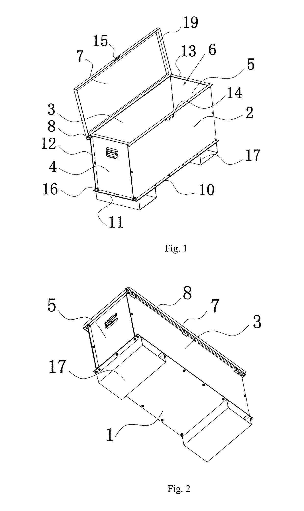
[0023]As shown in FIG. 1, a loaded pallet container of the present invention is provided, including a rectangular container body soleplate 1. U-shaped supporting feet 17 are secured on two sides in a direction of the length of a bottom surface of the container body soleplate 1. A front enclosure plate 2, a rear enclosure plate 3, a left enclosure plate 4 and a right enclosure plate 5 are all vertically secured on rims of four edges of an upper surface of the container body soleplate 1, correspondingly. A rectangular accommodating cavity 6 is enclosed by the container body soleplate 1, the front enclosure plate 2, the rear enclosure plate 3, the left enclosure plate 4 and the right enclosure plate 5 together. A cover 7 is matched and covered on an upper opening of the accommodating cavity 6. The container body soleplate 1, the front enclosure plate 2, the rear enclosure plate 3, the left enclosure plate 4, the right enclosure plate 5 and the cover 7 are made of aluminum alloy profile...

embodiment 2

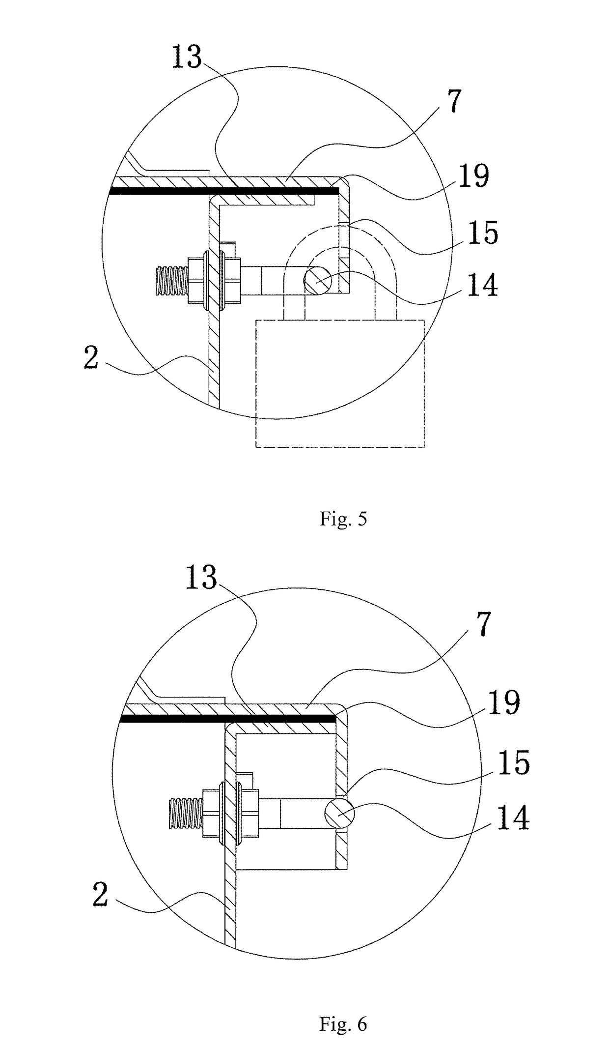
[0024]As shown in FIG. 6, the U-shaped lock cylinder 14 is matched and inserted into the lock hole 15, when the cover 7 is pushed to slide backward horizontally after the cover 7 is closed, and a roller is mounted at a corner of the bottom surface of the container body soleplate 1, respectively. The remaining is completely the same as Embodiment 1.

embodiment 3

[0025]U-shaped supporting sheet 17 are symmetrically secured on two sides in a direction of the length of the bottom surface of the container body soleplate 1, and a roller is mounted on a U-shaped supporting foot 17 corresponding to a corner of the bottom surface of the container body soleplate 1, respectively. The remaining is completely the same as Embodiment 2.


PUM


Abstract

A loaded pallet container includes a rectangular container body soleplate, a cover, a horizontal rotating shaft, a front enclosure plate, a rear enclosure plate, a left enclosure plate, and a right enclosure plate. A rectangular accommodating cavity is defined by the container body soleplate, the front enclosure plate, the rear enclosure plate, the left enclosure plate and the right enclosure plate. The cover covers an upper opening of the accommodating cavity and is connected to the horizontal rotating shaft through a horizontal long hole provided in each of the left side surface and the right side surface of the cover. The loaded pallet container is easy to transport, and has high strength, a cover that is easy to open and close, and a container body that is conveniently assembled and disassembled.

Description

TECHNICAL FIELD OF THE INVENTION[0001]The present invention relates to a container, in particular to a loaded pallet container having a cover easy to open and close and a container body convenient in disassembly and assembly, and being easy in storage and transportation.BACKGROUND OF THE INVENTION[0002]A pallet container or storage box having a loading function is mainly used for receiving goods in the storage and logistics industry, and when in use, required to be transported to the site for loading. At present, a commercially available loaded pallet container is generally a fixed container body structure made of wood or iron, and has a large volume; as it is impossible to disassemble such a loaded pallet container, the transportation is very inconvenient; and the cover is required to be disassembled completely during loading and unloading, this consumes both time and labor.[0003]Chinese Patent CN203714508U, titled “CONTAINER”, disclosed a container including a base frame; the base...

Claims


Application Information

Patent Timeline
Patent Type & Authority Patents(United States)
IPC IPC(8): B65D19/06B65D19/08B65D19/42
CPCB65D19/06B65D19/42B65D19/08B65D2519/00731B65D2519/00024B65D2519/00059B65D2519/00094B65D2519/00164B65D2519/00199B65D2519/00268B65D2519/00288B65D2519/00318B65D2519/00333B65D2519/00373B65D2519/00497B65D2519/00537B65D2519/00572B65D2519/00611B65D2519/00661B65D19/38B65D2519/00502B65D2519/00273
Inventor WENG, XINYUE
Owner NINGBO LANDPROFIT FAREAST IMP&EXP
Features
  • Generate Ideas
  • Intellectual Property
  • Life Sciences
  • Materials
  • Tech Scout
  • Unparalleled Data Quality
  • Higher Quality Content
  • 60% Fewer Hallucinations
Learn More