Control device for controlling printer to execute multi-pass printing

Active Publication Date: 2018-12-04
BROTHER KOGYO KK
View PDF8 Cites 0 Cited by
  • Summary
  • Abstract
  • Description
  • Claims
  • Application Information

AI Technical Summary

Benefits of technology

The present disclosure aims to provide a printing technique that prevents a decrease in printed image density resulting from deviation in the relative positions of dots.

Problems solved by technology

However, the conventional technique described above may inadvertently produce gaps between dots caused by deviation in the relative positions of dots formed during one main scan and dots formed during another main scan, potentially decreasing the density of the printed image.

Method used


Image

  • Control device for controlling printer to execute multi-pass printing
  • Control device for controlling printer to execute multi-pass printing
  • Control device for controlling printer to execute multi-pass printing

Examples


first embodiment

A. First Embodiment

[0022]A-1. Structure of a Printing Apparatus

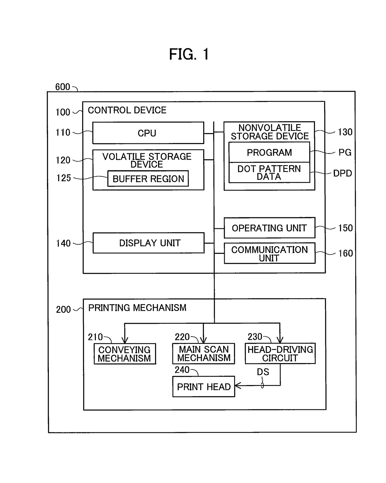
[0023]Next, embodiments of the present disclosure will be described while referring to the accompanying drawings. FIG. 1 is a block diagram showing the structure of a printing apparatus 600 according to the embodiments. The printing apparatus 600 is an inkjet printer that prints images on sheets of paper or another recording medium by forming dots on the paper with ink. The printing apparatus 600 includes a control device 100 for controlling all operations of the printing apparatus 600, and a printing mechanism 200 serving as the printer.

[0024]The control device 100 includes a central processing unit (CPU) 110 functioning as the controller; a volatile storage device 120, such as dynamic random-access memory (DRAM); a nonvolatile storage device 130, such as flash memory or a hard disk drive; a display unit 140, such as a liquid crystal display; an operating unit 150, such as a touchscreen superimposed on a liquid crystal ...

second embodiment

B. Second Embodiment

[0107]In a second embodiment of the present disclosure, the printing apparatus 600 performs two-pass printing for forming dots corresponding to k number of pixels in a single raster line oriented in the main scanning direction by distributing dot formation over two pass processes. FIG. 11 is a conceptual diagram illustrating two-pass printing according to the second embodiment. In FIG. 11, the position of the nozzle row NK relative to the sheet PM in the conveying direction is specified for each pass process, as in FIG. 5 described above.

[0108]In FIG. 11, the first (j=1) conveying process F1 is the process that conveys the sheet PM to its initial position. The feed amount for the second and subsequent conveying processes Fj (2≤j≤q) is one-half the total nozzle length D. Thus, in the second embodiment, two-pass printing is executed using nozzles over the total nozzle length D for each pass process and equal feed amounts between pass processes.

[0109]In FIG. 11, as ...

third embodiment

C. Third Embodiment

[0117]In the third embodiment, the printing apparatus 600 performs two-pass printing in partial areas of an image-forming region to form dots corresponding to k number of pixels in a single raster line oriented in the main scanning direction by distributing dot formation over two pass processes. The printing apparatus 600 also performs one-pass printing in other partial areas of the image-forming region to form dots corresponding to k number of pixels through a single pass process. FIG. 12 is a conceptual diagram for the printing process according to the third embodiment. In FIG. 12, as in FIG. 5, the position of the nozzle row NK relative to the sheet PM in the conveying direction is specified for each pass process.

[0118]The first (j=1) conveying process F1 is the process that conveys the sheet PM to its initial position. The feed amount for the second and subsequent conveying processes Fj (2≤j≤q) is two-thirds of the total nozzle length D. In the present embodim...


PUM


Abstract

In a control device, a controller is configured to perform: acquiring target image data; and controlling a printer to execute a first forming process forming dots on a first scanning range and a second forming process forming dots on a second scanning range. The first scanning range overlaps the second scanning range at an overlapping area. The overlapping area includes a first position corresponding to a first pixel and a second position corresponding to a second pixel. In a case where both a first pixel value and a second pixel value indicate forming a dot and the target image data satisfies a condition requiring that density in a region including the first pixel is equal to or more than a reference, the first forming process forms a dot at the first position and the second forming process forms a dot at both the first position and the second position.

Description

CROSS REFERENCE TO RELATED APPLICATION[0001]This application claims priority from Japanese Patent Application No. 2016-193428 filed Sep. 30, 2016. The entire content of the priority application is incorporated herein by reference.TECHNICAL FIELD[0002]The present disclosure relates to a method of controlling a printer to execute a printing operation, the printer including a conveying mechanism that conveys a printing medium, and a print head having a plurality of nozzles.BACKGROUND[0003]An inkjet printer known in the art forms dots on paper by repeatedly moving a print head in a main scanning direction (an operation called a “main scan”) and ejects ink from a plurality of nozzles formed in the print head during each main scan. However, this type of printer is susceptible to a problem called “banding” in the printed image that is caused by irregularities in the amounts that the sheets are conveyed, for example.[0004]For use by this type of printer, a technique that employs a plurality...

Claims


Application Information

Patent Timeline
IPC IPC(8): B41J2/045G06K9/38B41J25/00G06K9/46B41J2/21G06K15/10
CPCB41J2/04508B41J2/04586B41J2/2132B41J2/2139G06K15/102B41J2/2146B41J25/006G06K9/38G06K9/46B41J2/2142
Inventor YOSHIDA, YASUNARI
Owner BROTHER KOGYO KK
Why Eureka
Try Eureka