
Device and method for trephine alignment

a technology of trephine and ocular trephine, which is applied in the field of trephine alignment devices, can solve the problems of minimal training of tissue recovery technicians, difficult to prove, and inability to have the same resources as available, so as to facilitate ambient light and reduce human error

Active Publication Date: 2018-12-11
THISTLE KYLE
View PDF13 Cites 1 Cited by
  • Summary
  • Abstract
  • Description
  • Claims
  • Application Information

AI Technical Summary

Benefits of technology

The present invention is a device that attaches to a trephine to assist in the proper alignment of the trephine during eye surgery. The device fits trephines of different lengths and diameters, extends from the body of the trephine, provides a means for the user to visually confirm trephine fit, incorporates one or more visual reference structures, and reduces human error during trephine placement and manipulation. The device also facilitates ambient light to illuminate the trephine incising edge and provides a means for the user to visually confirm trephine fit.

Problems solved by technology

Although the overlapping indicator pointers may be useful at a number of distances, they may prove problematic the closer the user's vision approaches the top pointer, as it would obscure the bottom pointer.
Tissue banks do not have the same resources that are available to hospitals and tissue recovery technicians are minimally trained compared to the rigorous instruction that physicians receive.
If the scleral rim size is too small or too large in diameter, the tissue cannot be processed and utilized in keratoplasty surgeries for living patients.
Additionally, if the corneal tissue is contacted during the procedure this may result in corneal epithelial damage that may render the tissue unusable for transplant.
Placement of the larger diameter trephine on the sclera of the donor cadaver eye is estimated by the tissue recovery technician, resulting in inaccuracy that may render the surgically recovered cadaveric corneal tissue non-viable for transplant.

Method used


Image

  • Device and method for trephine alignment
  • Device and method for trephine alignment
  • Device and method for trephine alignment

Examples


Embodiment Construction

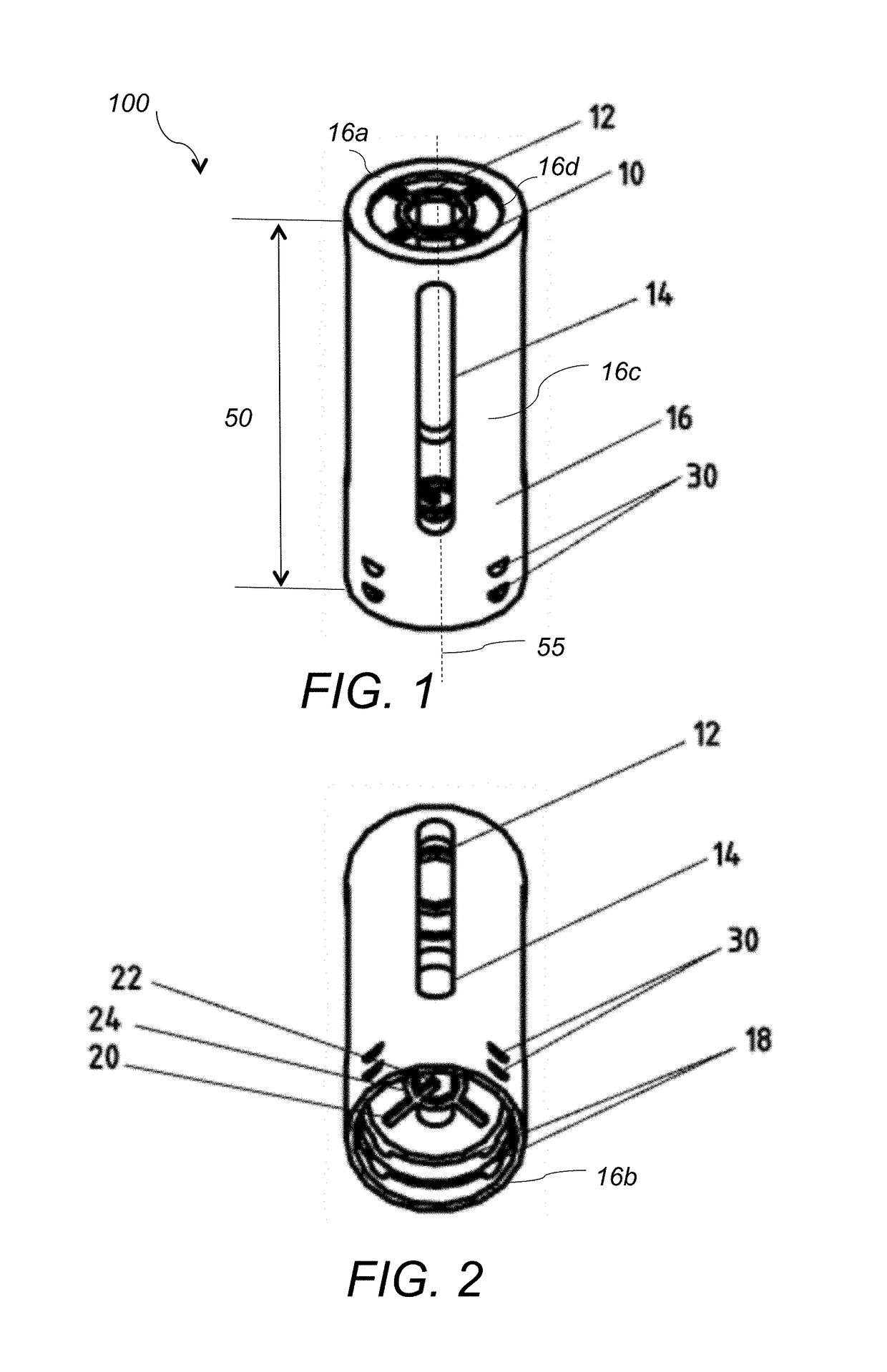
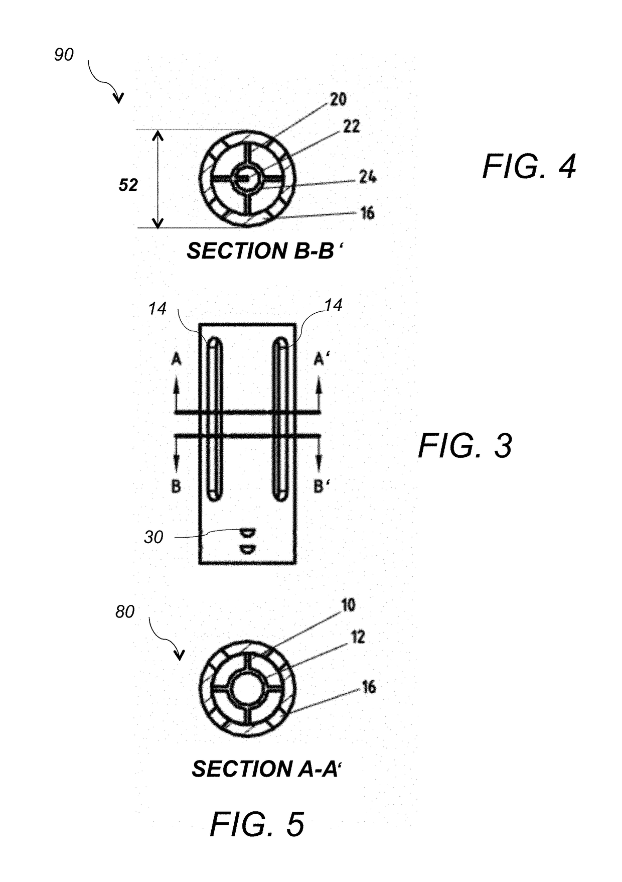
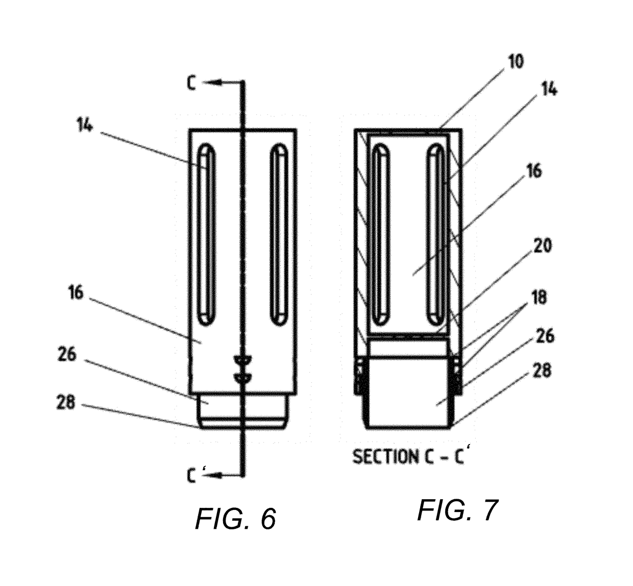
[0025]Referring to FIG. 1 and FIG. 2, a trephine alignment device 100 includes an elongated hollow cylindrical body 16 extending along axis 55 and having an open proximal end (top end) 16a, an open distal end (bottom end) 16b, a cylindrical outer surface 16c, and a cylindrical inner surface 16d. The hollow cylindrical body 16 has an appropriate length and width for allowing multiple finger placement, manual manipulation, and visual alignment. In one example, body 16 has a length 50 of 58 mm, an outer diameter 52 of 23.4 mm, and a body thickness at the top end of 3 mm. In another example, the body thickness at the bottom end is reduced by about 1 mm to incorporate trephines of different diameters, as will be described below. In one example, the body 16 is dimensioned to incorporate an 18 mm trephine and a 19.5 mm trephine. The 18 mm trephine has an outer diameter of 19.6 mm and the 19.5 mm trephine has an outer diameter of 21.1 mm. The body 16 is made of plastic or other material tha...


PUM


Abstract

A device for holding and aligning a trephine blade includes an elongated cylindrical component, a first alignment structure and a second alignment structure. The elongated cylindrical component extends along a first axis and comprises a hollow cylinder having an open proximal end, an open distal end, an inner cylindrical surface and an outer cylindrical surface. The first alignment structure is integral and co-planar with the proximal end and comprises a first circle attached to the inner cylindrical surface with one or more radially extending rods. The second alignment structure is arranged parallel to the first alignment structure within the hollow cylinder above the distal end and comprises a second circle attached to the inner cylindrical surface with one or more radially extending rods. The first and second circles are coaxial with the first axis and the first circle comprises a diameter that is greater than a diameter of the second circle.

Description

CROSS REFERENCE TO RELATED CO-PENDING APPLICATIONS[0001]This application claims the benefit of U.S. provisional application Ser. No. 62 / 274,371 filed on Jan. 4, 2016 and entitled Trephine Alignment Device, the contents of which are expressly incorporated herein by reference.FIELD OF THE INVENTION[0002]The present invention relates to a device and a method for trephine alignment and in particular to a device for an ocular trephine alignment.BACKGROUND OF THE INVENTION[0003]The present invention relates to medical devices, and specifically to surgical instruments with blades or “trephines.” A trephine is a surgical instrument with a cylindrical blade that is commonly used in medical procedures to create a circular incision around an area of interest. A trephine usually includes a hollow metal cylinder with one end of the cylinder having a sharp incising edge. Trephines are also used during ophthalmic surgery in order to correct a corneal defect of a living patient. Radial keratotomy, ...

Claims


Application Information

Patent Timeline
Patent Type & Authority Patents(United States)
IPC IPC(8): A61F9/013A61B17/3205A61B90/00
CPCA61F9/0133A61B17/32053A61B2090/395
Inventor THISTLE, KYLE
Owner THISTLE KYLE
Learn More