Component attachment with a transverse force-supporting surface

a technology of supporting surface and component, applied in the direction of vehicle components, pivoted suspension arms, resilient suspensions, etc., can solve the problems of mountings pulling away, adverse effects on the kinematics of the wheel suspension, etc., and achieve the effect of preventing effective gaping and efficiently and cost-effectively carrying ou

Inactive Publication Date: 2018-12-11
ZF FRIEDRICHSHAFEN AG
View PDF37 Cites 4 Cited by
  • Summary
  • Abstract
  • Description
  • Claims
  • Application Information

AI Technical Summary

Benefits of technology

[0005]A component connection for a wheel suspension of a motor vehicle is proposed, which comprises a control arm, in particular a track rod and / or a transverse control arm, and a connection component, in particular a wheel carrier, a vehicle body and / or an auxiliary frame of a motor vehicle. These are connected detachably to one another by fixing means, in particular by a bolt and / or a screw. At least at one of its ends the control arm has a mounting, in particular a rubber mounting having an inner sleeve. The fixing means presses the inner sleeve in the axial direction, with a first contact surface facing toward the connection component, against an abutment surface of the connection component. This braces the mounting, particularly its inner sleeve, axially against the connection component. To decouple the fixing means from transverse forces that may act upon it, or at least to minimize their effect, the connection component has a supporting surface. The inner sleeve rests against this supporting surface with a second contact surface. Relative to the abutment surface, the supporting surface is inclined in such manner that by means of it, transverse forces that occur in the radial direction in the area of the mounting can be supported. Because of this, compared with connections known from the prior art, the mounting connection can absorb larger transverse forces without the component connection being pulled apart, i.e. even when loaded the contact surfaces or the supporting surface of the inner sleeve and the connection component remain in contact all over and no gap is produced between the components even temporarily so that they move relative to one another. Furthermore, by virtue of the support provided by the supporting surface the fixing means can be made smaller, whereby the space occupied and the manufacturing costs can be reduced.
[0019]First, an inner sleeve with at least a fixed outer diameter and at least one first contact surface is made. In addition, a frictional and / or interlocking connection of the inner sleeve with the wheel-guiding component (multi-point control arm) is established. Furthermore, the connection component is made with at least one contact surface and at least one supporting surface serving for the later connection to the wheel-guiding component and with a bore that fits the outer diameter of the inner sleeve. The particular feature of the production method is that the outer diameter of the inner sleeve and the diameter of the bore are nominally the same size. In relation to their inner and outer diameters the inner sleeve and the bore fit. To be able to connect the wheel-guiding component to the connection component, the two components are made and then positioned and held in relation to one another in such manner that the wheel-guiding component and the connection component have their contact surfaces and / or supporting surfaces against or in one another. During this, care should be taken that the longitudinal axes of the components are at least very nearly aligned. The components are connected to one another with interlock, the connection component is joined to the wheel-guiding component in particular by screwing. Suitable fits for the connection between the wheel-guiding component and the connection component are preferably a transition or an interference fit. These fits minimize or exclude any play, so that gaping is effectively prevented.

Problems solved by technology

Since the fixing means is primarily designed to absorb tensile forces, the disadvantage of this type of connection is that if transverse forces occur the fixing means bend, whereby the mountings begin to pull away from the wheel carrier.
During this, the inner mounting sleeve lifts clear of the wheel carrier in one area, with the result that the kinematics of the wheel suspension are affected adversely since the components are no longer in contact with one another.

Method used


Image

  • Component attachment with a transverse force-supporting surface
  • Component attachment with a transverse force-supporting surface
  • Component attachment with a transverse force-supporting surface

Examples


Embodiment Construction

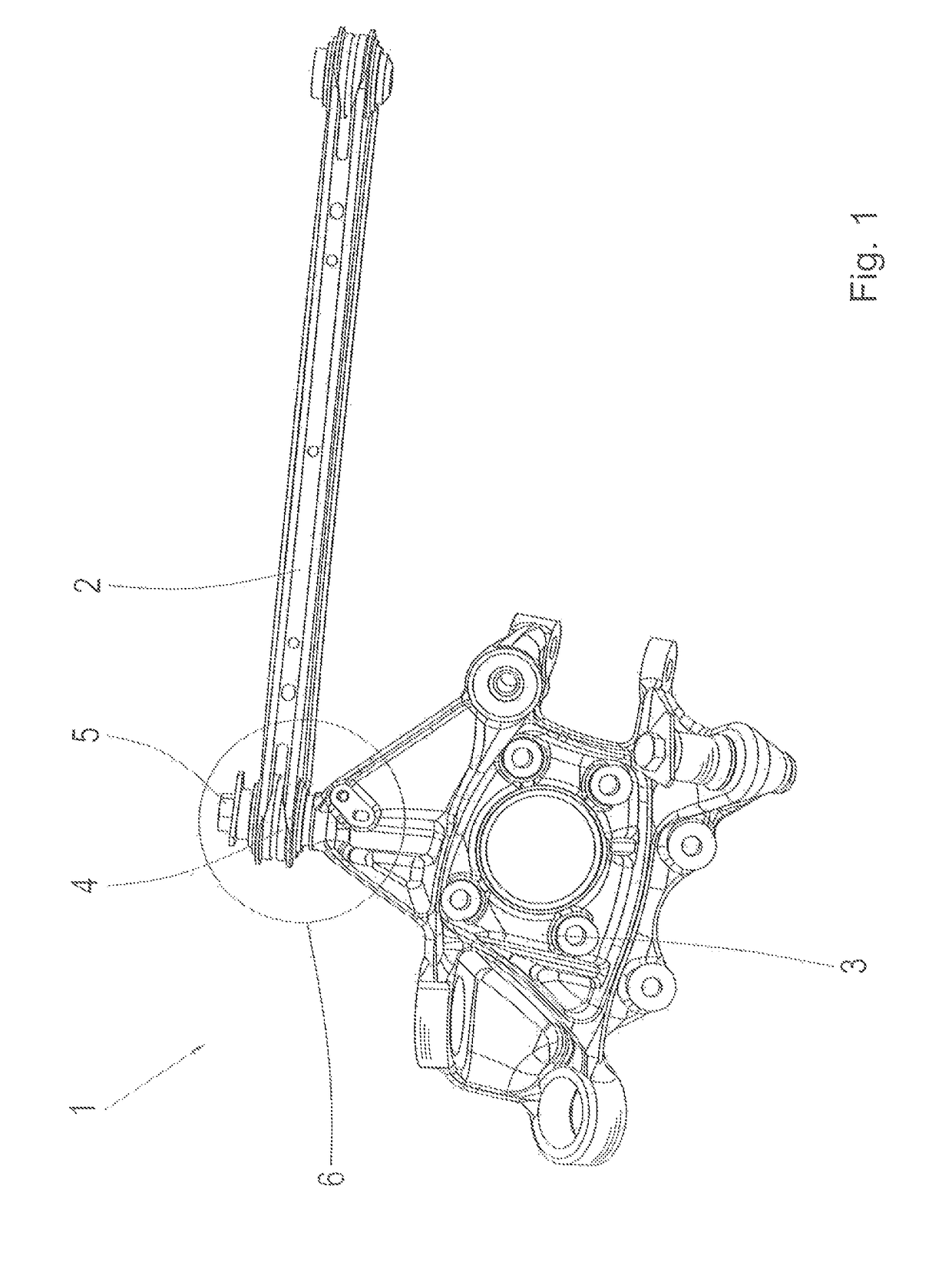
[0025]FIG. 1 shows a control arm arrangement 1, viewed in perspective. The control arm arrangement 1 comprises a control arm 2 and a connection component 3. In the example embodiment shown in FIG. 1, the connection component 3 is in the form of a wheel carrier. The control arm 2 is preferably a transverse control arm and / or a track rod. As shown in FIG. 1, the control arm 2 is articulated to the connection component 3 by means of a mounting 4. The mounting 4 is arranged on the end of the control arm 2 facing toward the connection component 3. In this area the control arm 2 has an eye in which the mounting 4 is held with interlock and / or by friction. In the area of the mounting 4 the control arm 2 is connected detachably to the connection component 3 or wheel carrier by fixing means, in particular by a screw-bolt.

[0026]According to FIG. 1, at its end remote from the connection component 3 the control arm 2 has a second mounting designed identically to the mounting 4, by means of whic...


PUM


Abstract

A component connection for a wheel suspension of a motor vehicle, with a control arm having a mounting, in particular a rubber mounting, at least at one of its ends. An inner sleeve and a connection component, in particular a wheel carrier, are fixed to one another by a fixing element. The fixing element presses a first contact surface of the inner sleeve, in the axial direction, toward the connection component against an abutment surface of the connection component. The connection component has a supporting surface against which a second contact surface of the inner sleeve rests. Furthermore, the supporting surface is inclined relative to the abutment surface in such a manner that transverse forces occurring, in the radial direction in the area of the mounting, can be supported.

Description

[0001]This application is a National Stage completion of PCT / EP2014 / 078142 filed Dec. 17, 2014, which claims priority from German patent application serial no. 10 2014 201 057.8 filed Jan. 22, 2014.FIELD OF THE INVENTION[0002]The present invention concerns a component connection. Furthermore, the invention concerns the use of a component connection in the chassis of a motor vehicle, as well as a method for producing a component connection, in particular in a chassis of a motor vehicle.BACKGROUND OF THE INVENTION[0003]In motor vehicle suspensions, in a generally familiar way, control arms are articulated to a wheel carrier, a vehicle body and / or an auxiliary frame. For this purpose, at least at one of their two ends the control arms have a mounting. Transverse control arms and track rods in particular are connected to the wheel carrier on the wheel side by way of a single-shear connection. In a single-shear connection an inner sleeve of the mounting is in contact at only one of its t...

Claims


Application Information

Patent Timeline
Patent Type & Authority Patents(United States)
IPC IPC(8): B60G3/02B60G3/20B60G7/00B60G7/02
CPCB60G3/02B60G3/202B60G7/008B60G7/02B60G2200/00B60G2206/8207B60G2204/14B60G2204/148B60G2204/41B60G2204/44B60G2206/82B60G2200/18
Inventor GRAEULER, DIRK
Owner ZF FRIEDRICHSHAFEN AG
Why Eureka
Try Eureka