Vessel head and tool and method for the production thereof

a technology which is applied in the field of vaulted heads and tools, can solve the problems of deformation anomalies, particularly difficult, and difficult production of vaulted heads, and achieve the effects of improving pressure resistance, increasing the suitability of such a vessel head, and increasing the weight and price (material cost) of the head

Active Publication Date: 2018-12-11
THIELMANN
View PDF11 Cites 1 Cited by
  • Summary
  • Abstract
  • Description
  • Claims
  • Application Information

AI Technical Summary

Benefits of technology

[0015]The shaping according to the invention also enables improved pressure resistance (internal excess pressure acting on the concave wall section of the vessel head) so as to increase the suitability of such a vessel head for a pressure vessel. This allows to reduce the minimum wall thickness and thus the weight and price (material costs) of the head while ensuring the same stability. Moreover the tension transitions in the flat curved cylindrical shell section can be configured smoother.

Problems solved by technology

Manufacturing these vaulted heads is particularly challenging for non-circular tank cross-sections.
What is particularly difficult is integrally flanging, integrally forming the knuckle area and the straight flange.
For another, the usual head shapes where a uniform vault radius makes a transition to a uniform knuckle radius in the dish area are suitable only to a limited extent for pressing and in particular deep-drawing processes since the shapes of non-circular vessel cross-sections show different and asymmetrical curve shapes which, together with the productional, asymmetrical strengths of rolled metal sheets may result in deformation anomalies.
These may include creases, dents, and unintentional thinning or thickening in the starting material generated in the deformation process.
Therefore these heads are manufactured in complex, manual shaping processes or joined together from prefabricated component parts.
These vessel heads cannot be manufactured with simple deep-drawing processes (one-stage) at all or at best showing the quality defects indicated above.

Method used


Image

  • Vessel head and tool and method for the production thereof
  • Vessel head and tool and method for the production thereof
  • Vessel head and tool and method for the production thereof

Examples


Embodiment Construction

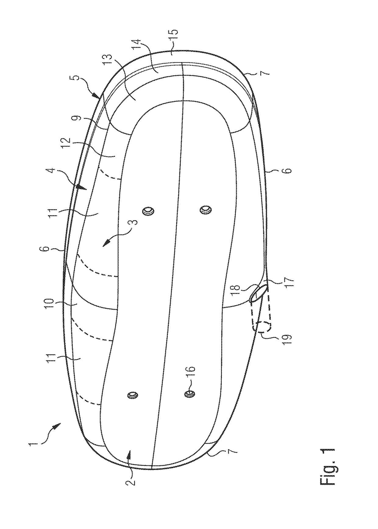
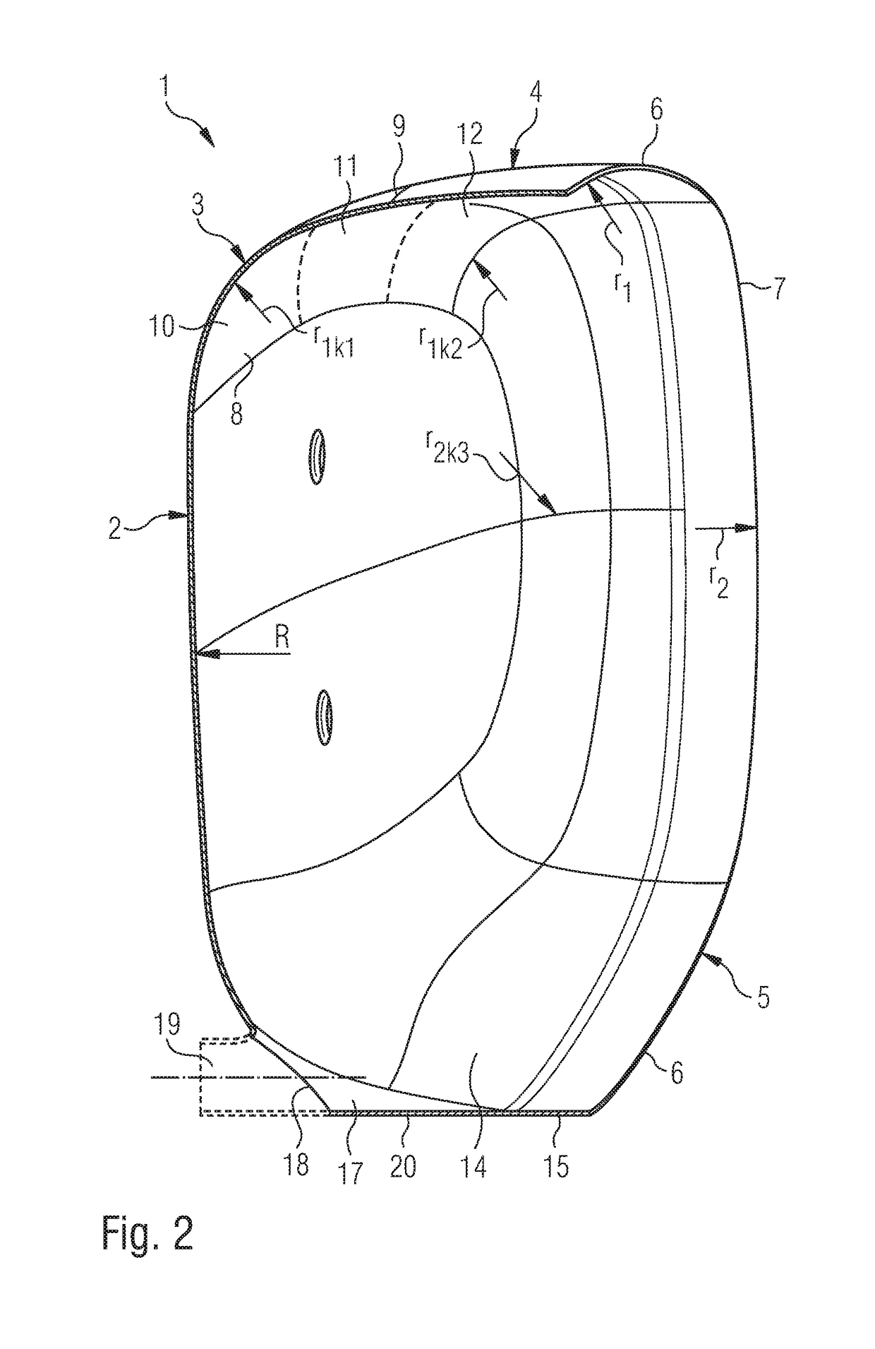
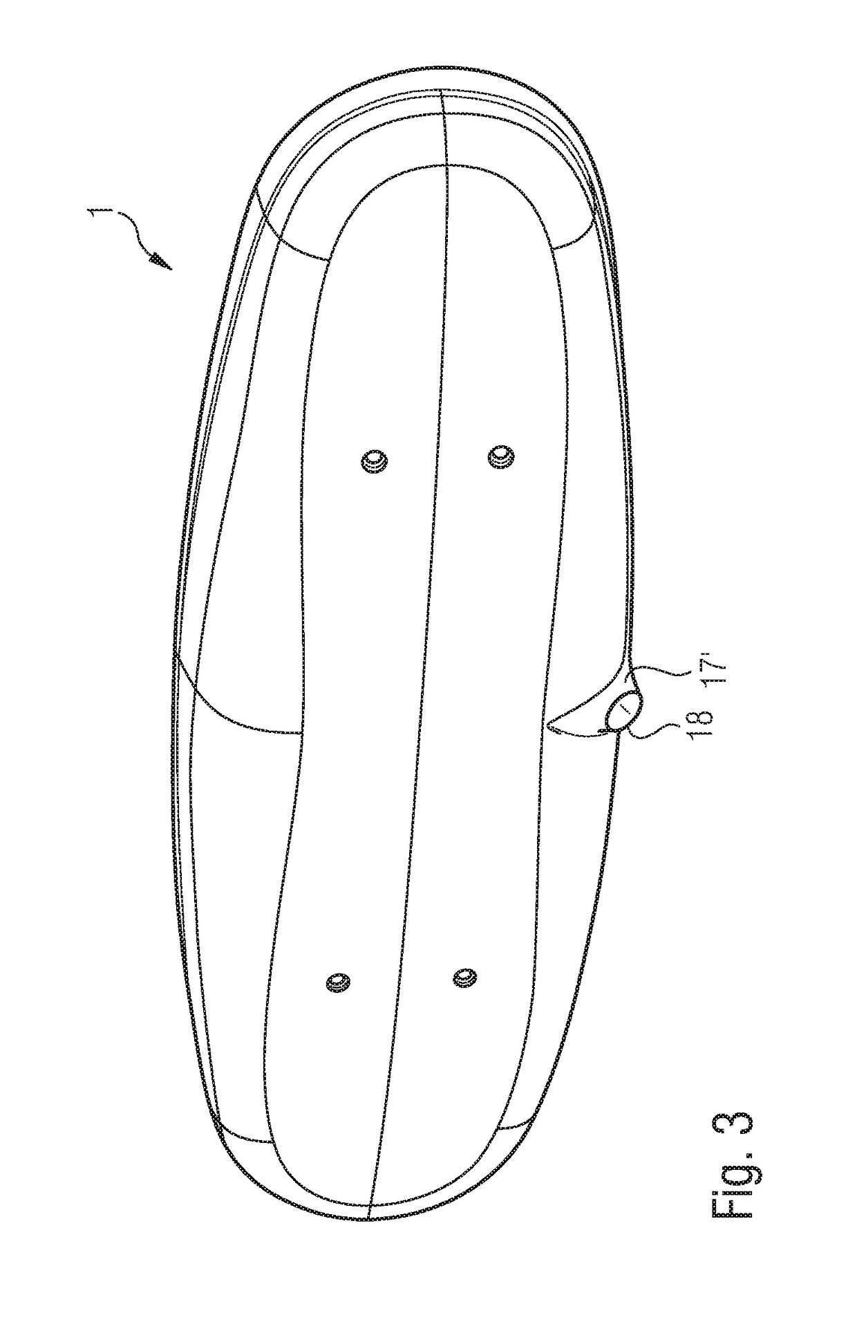
[0026]FIG. 1 illustrates an embodiment in accordance with the present invention. A detailed description will now follow general explanations on the embodiments.

[0027]In conjunction with this application the term “vault” is used so as to mean a surface showing curves in multiple axes, as in a spherical shape. Whereas the term “curve” denotes a surface curved in one axis, as in a cylinder shape.

[0028]Furthermore the following specific meaning applies with regard to the knuckle area of a head which is vaulted according to the definition above where the knuckle area shows (optionally different) curves. For one, the curve that is indicated by the so-called knuckle radius or the knuckle curve. This knuckle radius lies in a sectional plane that is normal to the knuckle or head surface, indicating the curve of the knuckle area in this plane. In the case of a circular knuckle area the knuckle surface describes a torus or a section of a torus respectively (enveloping surface forming a circle ...


PUM

PropertyMeasurementUnit
diametersaaaaaaaaaa
diametersaaaaaaaaaa
diametersaaaaaaaaaa

Abstract

The invention relates to a vessel head (1) for a vessel (30), comprising: a vaulted dish area (2) having a vault radius R, a connecting contour (5) comprising in a first contour section (6) a first radius of curvature (r1) and in a second contour section (7), a second radius of curvature (r2), wherein the first radius of curvature (r1) is larger than the second radius of curvature (r2) and a knuckle area (3) surrounding the dish area (2) and tracing the connecting contour (5) is configured between the connecting contour (5) and the dish area (2) comprising, extending along the first contour section (6), a first knuckle section (10) having a first knuckle radius (r1k1) and a second knuckle section (12) having a second knuckle radius (r1k2). The invention further relates to a tool and a method of manufacturing such a vessel head (1).

Description

FIELD OF THE INVENTION[0001]The present invention relates to a vessel head and a tool and to a method for the production thereof.BACKGROUND OF THE INVENTION[0002]In tank and apparatus construction, various vessel heads are known. Vessel heads tend to be vaulted sheet metal elements which serve to close the ends of usually cylindrical vessels or to subdivide the same into a number of compartments.[0003]The actual vessels are usually cylindrical in shape, showing different cross-sections (e.g. circular, elliptical, dual-shell, quadruple-shell, box-shaped). The outer vessel wall is formed of one or more curved sheet metal element(s) (manufactured by rolling), showing a tubular shape and the pertaining cross-sectional geometry. The ends of such a shell ring are closed with suitable vessel heads. To this end the vessel heads are usually welded to the shell ring. To this end the vessel head comprises a connecting contour corresponding to the shell ring so that the shell and the head abut ...

Claims


Application Information

Patent Timeline
Patent Type & Authority Patents(United States)
IPC IPC(8): B65D88/12B21D22/20B21D51/18
CPCB65D88/128B21D51/18B21D22/20
Inventor CRONACHER, FRANK
Owner THIELMANN
Why Eureka
Try Eureka