Digital image processing device and associated methodology of performing touch-based image scaling
a digital image processing and image scaling technology, applied in the field of digital image processing devices, can solve problems such as complex operation in comparison to single-touch operation, and achieve the effect of improving operability and easy touch
- Summary
- Abstract
- Description
- Claims
- Application Information
AI Technical Summary
Benefits of technology
Problems solved by technology
Method used
Image
Examples
first embodiment
1. First Embodiment
[0026]1.1 Outline of First Embodiment
[0027]First, an outline of a first embodiment will be explained. It should be noted that after the outline is explained, specific examples of the present embodiment will be explained.
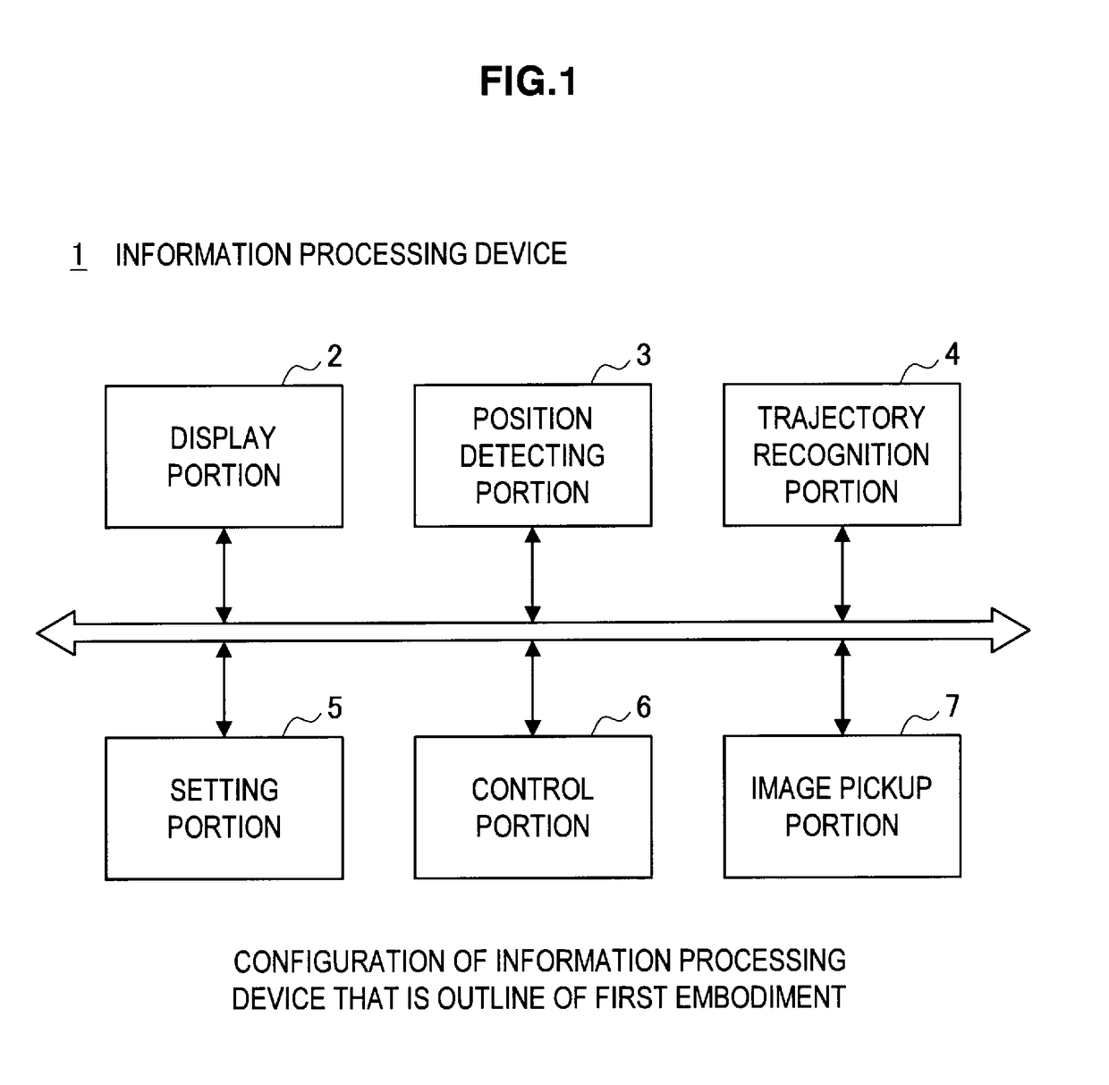
[0028]The reference numeral 1 in FIG. 1 indicates an information processing device. The information processing device 1 has a display portion 2 that displays images. Further, the information processing device 1 has a position detecting portion 3 that detects a touch position on a display screen of the display portion 2. In addition, the information processing device 1 has a trajectory recognition portion 4 that, when the touch position detected by the position detecting portion 3 moves, recognizes a single trajectory.
[0029]Additionally, the information processing device 1 has a setting portion 5 that, based on the single trajectory recognized by the trajectory recognition portion 4, sets a center point (focal center) and a ratio that are used to pe...
second embodiment
2. Second Embodiment
[0146]A second embodiment will next be explained. In the above-described first embodiment, when the finger is moved such that it traces the circle, the zoom ratio is set in accordance with the amount of the circle traced (namely, in accordance with a length of the circular arc).
[0147]In contrast, in the second embodiment, the zoom ratio is not set in accordance with the amount of the circle traced, but is set in accordance with a size of the circle traced.
[0148]Note that, the configuration of the DSC 100 is substantially the same as in the first embodiment, and the first embodiment is therefore referred to. Accordingly, here, only a zoom method is explained.
[0149]In a similar manner to the first embodiment, when switched to the photo mode, the CPU 110 displays the monitoring image Mp on the touch screen 109, as shown in FIG. 4.
[0150]Here, as shown in FIG. 9 and FIG. 10, the CPU 110 performs the zoom in operation when the touch operation is performed in which the ...
embodiment 1
3.1 Other Embodiment 1
[0168]In the above-described first and second embodiments, when in the playback mode, when the touch operation is performed in which the finger is moved to trace the circle in the clockwise direction, the CPU 110 of the DSC 100 scales up the playback image being displayed on the touch screen 109.
[0169]At this time, a section that is outside the traced circle on a displayed playback image Sp may remain the same and a section that is inside the traced circle may be scaled up, as shown in FIG. 12.
[0170]More specifically, when the touch operation is performed in which the finger is moved to trace the circle in the clockwise direction, the CPU 110 identifies the section inside the traced circle on the playback image Sp.
[0171]The CPU 110 then scales up the section inside the traced circle, centering on the screen coordinates X that are the center point of the traced circle, and using a scale-up ratio corresponding to the amount of the circle traced. Further, the CPU ...
PUM
 Abstract
Description
Claims
Application Information
 - R&D
- Intellectual Property
- Life Sciences
- Materials
- Tech Scout
- Unparalleled Data Quality
- Higher Quality Content
- 60% Fewer Hallucinations
Browse by: Latest US Patents, China's latest patents, Technical Efficacy Thesaurus, Application Domain, Technology Topic, Popular Technical Reports.
© 2025 PatSnap. All rights reserved.Legal|Privacy policy|Modern Slavery Act Transparency Statement|Sitemap|About US| Contact US: help@patsnap.com


