Patch cord connecting metal terminal having a pushbutton on a lateral side of a resilient arm

Active Publication Date: 2018-12-11
XIAMEN GUANG WANG IND
View PDF10 Cites 2 Cited by
  • Summary
  • Abstract
  • Description
  • Claims
  • Application Information

AI Technical Summary

Benefits of technology

[0003]The primary objective of the present invention is to provide a pushbutton-equipped patch cord connecting metal terminal and

Problems solved by technology

The existing connectors for connecting patch cords are structurally complex, making their manufacturing require considerable material and significant costs, yet their ope

Method used


Image

  • Patch cord connecting metal terminal having a pushbutton on a lateral side of a resilient arm
  • Patch cord connecting metal terminal having a pushbutton on a lateral side of a resilient arm
  • Patch cord connecting metal terminal having a pushbutton on a lateral side of a resilient arm

Examples


first embodiment

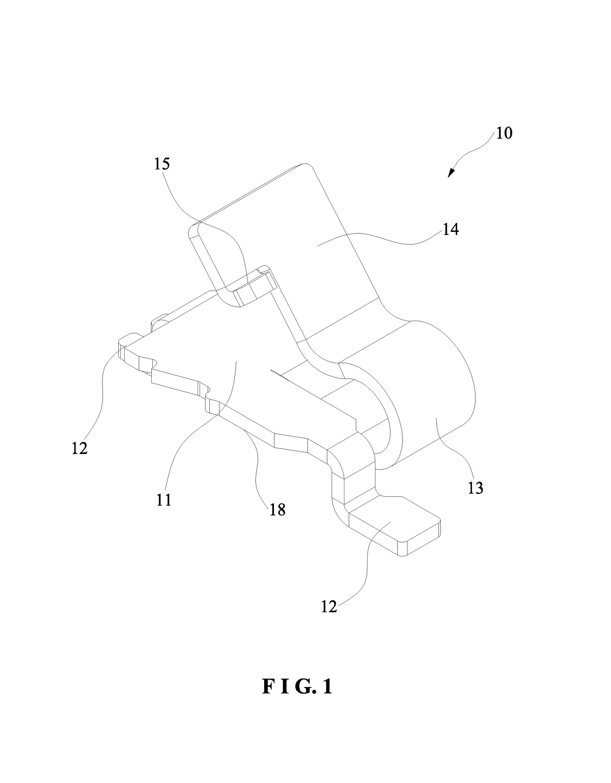
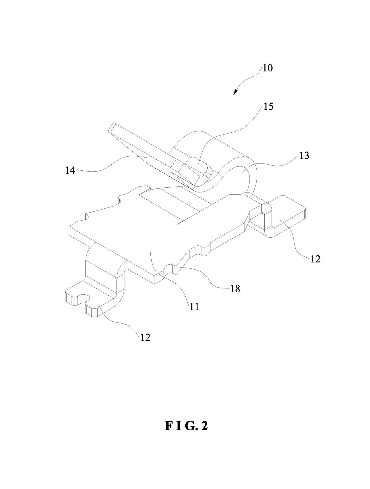
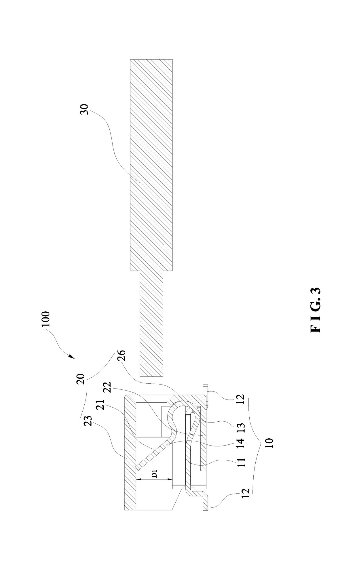
[0023]Based on the metal terminal 10, the present invention further discloses a pushbutton-equipped patch cord connector 100, which comprises the metal terminal 10 and a housing seat 20. The metal terminal 10 is just as described previously and repeated description is herein omitted. The housing seat 20 has a box-like shape with an accommodating chamber 21 running through its front and back. The metal terminal 10 is fixed in the accommodating chamber 21, with the weld legs 12 exposed at the bottom 22 of the housing seat 20 to contact a circuit board (a conventional component, not shown). The resilient arm 14 and the top 23 of the housing seat 20 is separated by a distance D1 allowing insertion. As shown in FIG. 3, D1 is measured from the bottom of the resilient arm 14 to the lower surface of the top 23. The housing seat 20 is formed with a push window 24 corresponding to the pushbutton 15 for easy push.

second embodiment

[0024]As shown in FIG. 5 through FIG. 8, in the pushbutton-equipped patch cord connecting metal terminal 10 of the present invention, which is designed based on the previous embodiment, the weld legs 12 are formed at the front and rear ends of the base 1, by, for example, bending the front and rear ends of the base 1 downward to form the weld legs 12, with the weld leg 12 at the rear end having its tail end bent upward to form an upright brace 16. The top of the brace 16 is then bent forward to form a horizontal upper contact surface 17 that is parallel to a horizontal portion of the base 11 as shown in FIG. 7. The upper contact surface 17 is located above the resilient arm 14 without covering the pushbutton 15 so as not to interfere with the pushing operation. The upper contact surface 17 and the resilient arm 14 are separated by a distance D2 so as to provide upper and lower contacts for the patch cord 30 to connect. As shown in FIG. 7, D2 is measured from a point on the resilient...


PUM


Abstract

A pushbutton-equipped patch cord connecting metal terminal is disclosed. The metal terminal has a base on which weld legs are formed. The base has its front part bent backward to form an arc-shaped resilient portion. The arc-shaped resilient portion has its tail end extending backward to form a tilted resilient arm that points the upper rear of the metal terminal. A pushbutton is formed at a lateral of the resilient arm. Also provided is a patch cord connector is composed of the metal terminal and a housing seat. The metal terminal and the connector are structurally simple and easy to use, while ensuring good electrical connection to a patch cord as well as convenient repeated plugging and unplugging of the patch cord.

Description

BACKGROUND OF THE INVENTION1. Technical Field[0001]The present invention relates to electrical connectors, and more particularly to a patch cord connecting metal terminal with a pushbutton and a patch cord connector with a pushbutton.2. Description of Related Art[0002]The existing connectors for connecting patch cords are structurally complex, making their manufacturing require considerable material and significant costs, yet their operation is inconvenient. Besides, after connected to or assembled with such a connector, a patch cord is hard to be unplugged without using a tool or an auxiliary structure. Hence, there is a need for a patch cord connecting metal terminal and a connector having a pushbutton formed thereon.SUMMARY OF THE INVENTION[0003]The primary objective of the present invention is to provide a pushbutton-equipped patch cord connecting metal terminal and a pushbutton-equipped patch cord connector, which are structurally simple and facilitate plugging and unplugging o...

Claims


Application Information

Patent Timeline
IPC IPC(8): H01R4/48H01R4/2429H01R13/506H01R13/518H01R4/02H01R13/641H01R31/06H04Q1/14H01R13/58
CPCH01R4/2429H01R13/506H01R13/518H01R4/029H01R13/641H01R31/06H01R4/4836H04Q1/149H01R13/58H01R12/515H01R12/57H04Q1/135H01R4/48275H01R4/48365
Inventor CHEN, BINGSHUI
Owner XIAMEN GUANG WANG IND
Why Eureka
Try Eureka