Systems and methods for spray cooling

a technology of spray cooling and cooling system, applied in the field of spray cooling system, can solve the problems of increasing system size and complexity, and achieve the effect of reducing the size and complexity of the cooling system and improving reliability

Active Publication Date: 2018-12-18
NAT TECH & ENG SOLUTIONS OF SANDIA LLC
View PDF6 Cites 4 Cited by
  • Summary
  • Abstract
  • Description
  • Claims
  • Application Information

AI Technical Summary

Benefits of technology

[0012]The disclosed ejectors are solid-state devices that use high-energy fluid in the form of vapor to entrain and drive a lower-energy liquid fluid through an in-line converging-diverging nozzle. The high-energy vapor is created from heat received from a high-heat flux, high temperature surface to be cooled. The ejectors are a non-moving form of a turbo-compressor that is directly driven by fluid vaporizing off of the heated surface. The vapor provides flow to the spray nozzle, supplanting external equipment and reducing the size and complexity of the cooling system while also improving reliability.

Problems solved by technology

These nozzles are supplied by external fluid conditioning and pumping equipment that require external power and increase both the size and complexity of the system.

Method used


Image

  • Systems and methods for spray cooling
  • Systems and methods for spray cooling

Examples


Embodiment Construction

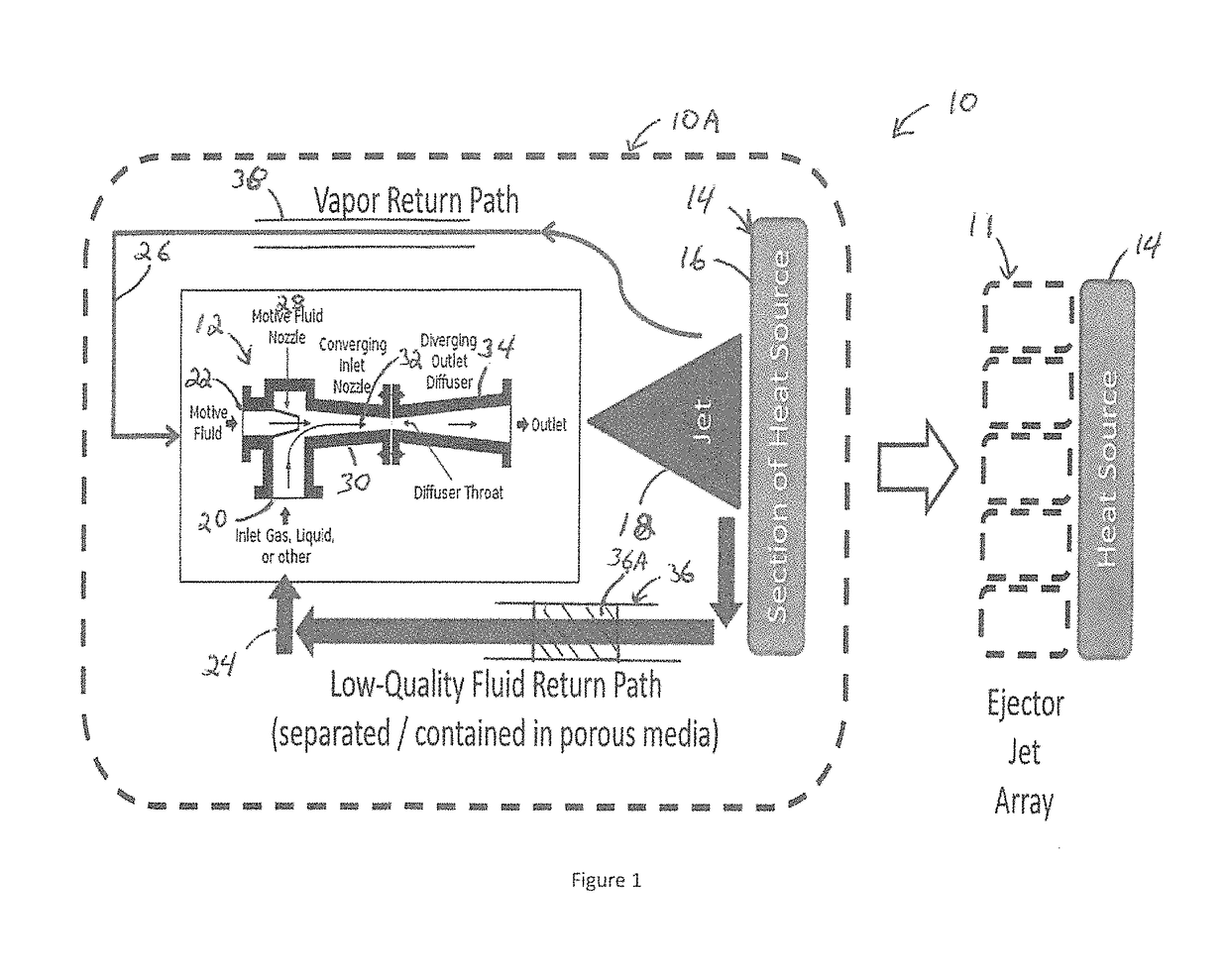
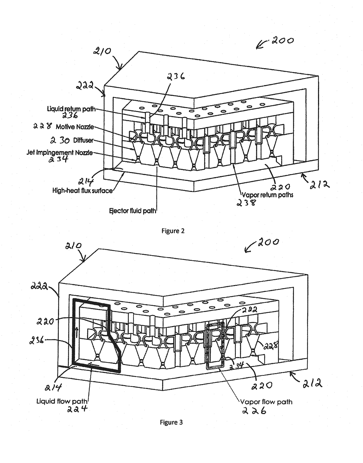
[0016]The present disclosure is directed to systems that include one or more solid-state micro-ejectors (ejectors) to form jets of cooling fluid to cool a high heat flux, high temperature surface. The ejectors are self-powered, meaning that the energy removed from the high temperature surface in the form of heat is used to drive the fluid flow through the ejectors. The ejectors include an injection nozzle that receives high-energy vapor created at the high temperature surface to entrain and drive a lower-energy fluid through an in-line converging-diverging nozzle within the ejectors, effectively acting as a solid-state turbo-compressor or turbo-pump. The ejectors are arranged adjacent the heated surface to provide direct spray cooling of the cooling fluid onto the heated surface.

[0017]The present disclosure is further directed to cooling methods that include producing vapor at a high temperature surface that is routed to an injection nozzle in an ejector, while liquid at the high te...


PUM


Abstract

The present disclosure is directed to systems, devices and methods for cooling a surface with a plurality of ejectors. The fluid provided to the micro-ejectors includes vapor formed at the surface. The vapor provides the driving force for driving fluid through the micro-ejectors.

Description

CROSS-REFERENCE TO RELATED APPLICATIONS[0001]This application claims priority to U.S. Provisional Patent Application Ser. No. 62 / 240,100, entitled “SYSTEMS AND METHODS FOR SPRAY COOLING,” by Matthew Carlson, filed Oct. 12, 2015, the disclosure of which is incorporated herein by reference in its entirety.STATEMENT CONCERNING FEDERALLY-SPONSORED RESEARCH[0002]This invention was developed under Contract DE-AC04-94AL85000 between Sandia Corporation and the United States Department of Energy. The U.S. Government has certain rights in this invention.FIELD OF THE INVENTION[0003]The present invention is directed towards cooling, and more particularly directed to spay cooling systems and methods that use the heat removed from an object to be cooled to drive cooling fluid flow.BACKGROUND OF THE INVENTION[0004]Current spray-cooling equipment uses an arrangement of spray-cooling nozzles to direct a coolant at a heated surface to provide cooling for extreme heat fluxes (above 100 W / cm^2). These ...

Claims


Application Information

Patent Timeline
Patent Type & Authority Patents(United States)
IPC IPC(8): F28D15/02F28D15/04F28F13/08
CPCF28D15/02F28D15/04F28D15/046F28F13/08F28F2250/08F28C3/08G21B1/13G21C15/00H01L23/427H01L23/4735H05K7/20345Y02E30/30
Inventor CARLSON, MATTHEW DAVID
Owner NAT TECH & ENG SOLUTIONS OF SANDIA LLC
Why Eureka
Try Eureka