System and Method For a Self-Referencing Interferometer

a self-referencing and interferometer technology, applied in the field of interferometers, can solve the problems of limiting the implementation of interferometers, the number of technical limitations of prior art interferometers, and the size of the components is large, so as to improve the beam quality, reduce the size and complexity of components, and improve the spatial phase shifting assembly

Active Publication Date: 2014-05-22
LEIDOS
View PDF6 Cites 3 Cited by
  • Summary
  • Abstract
  • Description
  • Claims
  • Application Information

AI Technical Summary

Benefits of technology

[0012]The embodiments of the present invention provide for an improved interferometer. The embodiments of the present invention improve upon prior art interferometers by reducing the size and complexity of the components of the interferometer.
[0013]In a first exemplary embodiment, the interferometer comprises an improved spatial phase shifting assembly. The improved spatial phase shifting assembly comprises a first interface that divides a signal beam into two components and divides a reference beam into two components. The first interface combines a first component of the signal beam with a first component of the reference beam producing a first beam pair and combines a second component of the signal beam with a second component of the reference beam producing a second beam pair. The first beam pair exits the first interface and passes through a half wave plate. The second beam pair exits the first interface and passes through a half wave plate, a quarter wave plate, and an optical component to adjust the alignment and conjugate image location of the beam path. A second interface divides the first and second beam pairs again so that four beam pairs exit the second interface. Each of the four beam pairs comprises a combination of a signal beam component and a reference beam component. Two of the four beam pairs pass through an optical component to adjust the alignment and conjugate image location of the beam path. The reference beam component and signal beam component of each pair combine to produce an interference pattern. The interference pattern is detected when each beam pair reaches a wave front sensor camera. Each of the four beam pairs also has a different, known relative phase shift between the signal component and the reference component. The wave front sensor processor uses the interference patterns created by the phase differences for each of the four beam pairs to identify any aberrations in the signal beam. The identified aberrations can be used in an adaptive optics system to control a spatial light modulator to correct the aberrations in the signal beam and improve beam quality.
[0014]In a second exemplary embodiment, a self-referencing interferometer uses an improved method to process an input signal. The method comprises receiving the input beam at the interferometer and splitting the input beam into a signal beam and a reference beam. The reference beam is transmitted through a single mode fiber shunt to remove aberrations in the reference beam. The reference beam and the signal beam are recombined by an optical component so that there is a defined relative tilt between the signal beam and reference beam. The recombined signal beam and reference beam are transmitted through an anamorphic optical relay, such as a crossed cylindrical lens relay, and to a wave front sensor camera. The wave front sensor processor analyzes the interference pattern produced by the recombined signal beam and reference beam in order to identify any aberrations in the signal beam. Identified aberrations can be used in an adaptive optics system to control a spatial light modulator to correct the aberrations in the signal beam and improve beam quality.

Problems solved by technology

The limitations with prior art interferometers are that they can be large in size and can weigh several pounds or more, limiting their implementation.
There are a number of technical limitations with prior art interferometers as well.
When a signal beam and a reference beam do not travel the same path within the interferometer, the two beams may be subject to aberrations that are not common to the paths of each beam.
Since the interferometer measures the phase differences between the two beams, non-common path aberrations distort the desired measurement.
Designing an interferometer to correct for these aberrations adds to the complexity of the interferometer.
The numerous optical surfaces limit the optical throughput of the spatial phase shifting assembly and worsen the problem of non-common path aberrations.
Furthermore, having numerous custom optical elements and a custom mounting assembly in a conventional spatial phase shifting assembly greatly increases the cost of the assembly.
The weight and size of conventional spatial phase shifting assemblies also limits prior art interferometers.
Accordingly, the weight and size of conventional spatial phase shifting assemblies limits how interferometers can be implemented and in which applications they can be used.
Another limitation in conventional interferometers is the length of the single mode fiber through which the reference beam passes.
Finally, the polarization requirements of a conventional interferometer using a spatial phase shifting assembly such as the one illustrated in FIGS. 1A and 1B further limit implementation of conventional interferometers for directed energy and laser communications applications.
Furthermore, the length of the reference fiber creates a greater probability that mechanical and thermal disturbances can alter the polarization of the reference beam and reduce the measurement accuracy of the interferometer.

Method used


Image

  • System and Method For a Self-Referencing Interferometer
  • System and Method For a Self-Referencing Interferometer
  • System and Method For a Self-Referencing Interferometer

Examples


Embodiment Construction

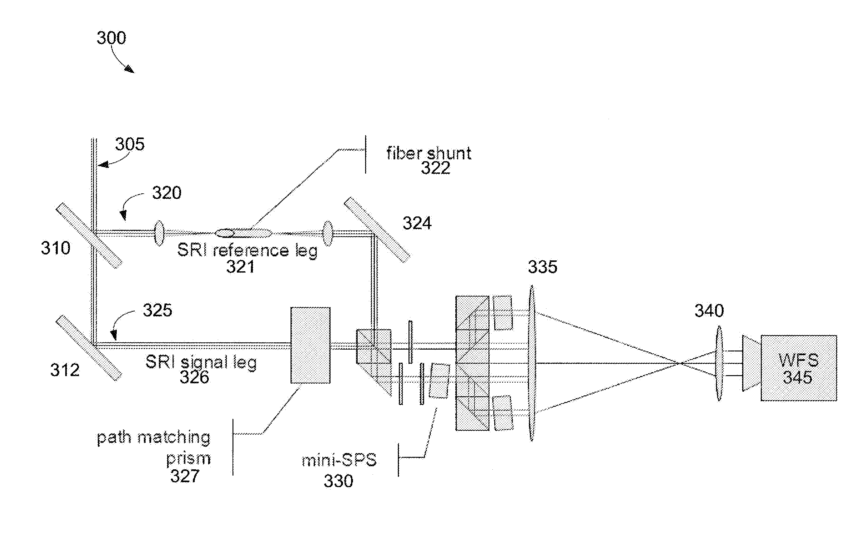
[0026]The invention is directed to components and methods for improved interferometers. Although the exemplary embodiments of the improved interferometers will be described in the following text and the associated figures, those skilled in the art will recognize that the exemplary embodiments can be modified in various ways within the scope of the invention. For example, the exemplary embodiments described herein include certain conventional components such as lenses and mirrors. Those of skill in the art will recognize that various different types of lenses and mirrors can be substituted for the conventional components described herein. Those of skill in the art also will recognize that the configuration of the conventional lenses and mirrors described herein can be modified within the scope of the invention.

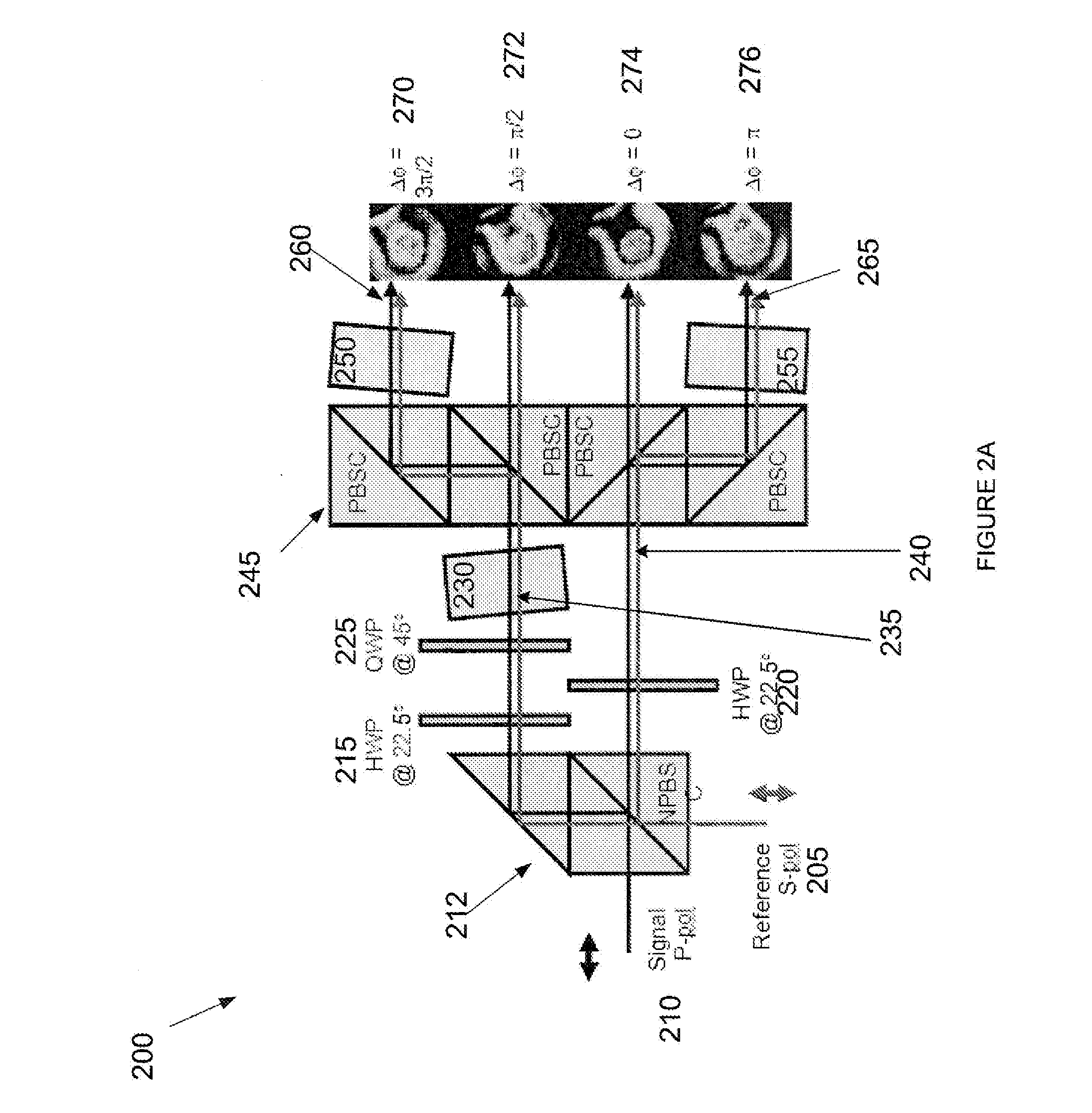
[0027]Turning to FIG. 2A, an exemplary embodiment of a miniature spatial phase shifter 200 is illustrated. The miniature spatial phase shifter 200 improves upon several of the ...


PUM


Abstract

Systems and methods are described herein for a self-referencing interferometer. The interferometer can comprise an improved spatial phase shifter that reduces the number of components, size and complexity of the spatial phase shifter and maintains a common path for a combined reference beam and signal beam. The self-referencing interferometer further comprises a single mode fiber shunt for filtering the reference beam and further reducing the size of the interferometer. The angle of the reference beam can be tilted before being recombined with the single beam which further simplifies the spatial phase shifting component of the interferometer.

Description

CROSS-REFERENCE TO RELATED APPLICATIONS[0001]This application is a divisional of U.S. patent application Ser. No. 12 / 839,520, filed Jul. 20, 2010, entitled “SYSTEM AND METHOD FOR A SELF-REFERENCING INTERFEROMTER,” which is incorporated herein by reference in its entirety.BACKGROUND OF THE INVENTION[0002]1. Field of the Invention[0003]The present invention relates generally to the field of interferometers and more particularly to a self-referencing interferometer that uses spatial phase shifting to reconstruct optical wave fronts.[0004]2. Description of the Related Art[0005]Phase shifting interferometers used in directed energy or laser communications applications typically consist of a light source that is split into two beams—a reference beam and a signal beam. The two light beams travel different paths, the reference beam is spatially filtered, and then the beams are recombined in such a way that the wave front of the signal beam can be determined. Phase shifting interferometry ca...

Claims


Application Information

Patent Timeline
Patent Type & Authority Applications(United States)
IPC IPC(8): G01B9/02
CPCG01B9/02097G01B9/02081G01B2290/70
Inventor RHOADARMER, TROYBERG, ERIC
Owner LEIDOS
Why Eureka
Try Eureka