Prime mover with recovered energy driven compression of the working fluid

a working fluid and moving device technology, applied in the direction of engine manufacturing, mechanical equipment, machines/engines, etc., can solve the problems of high heat exchanger terminal temperature difference relative, rotor stress limitation, and inefficient motor vehicle and stationary distributed electric generation size range, etc., to reduce size and complexity, reduce the effect of compression operation and increasing thermodynamic cycle efficiency

Active Publication Date: 2016-11-15
KAUFMAN JAY STEPHEN
View PDF6 Cites 4 Cited by
  • Summary
  • Abstract
  • Description
  • Claims
  • Application Information

AI Technical Summary

Benefits of technology

[0024]The prime mover and associated energy recovery systems of the present invention have application in a capacity range of approximately 20 kWe to 150 kWe in which speed of an expansion engine such as a gas turbine is reduced by operation in a compression ratio range of approximately 1.1 to 2.5. Problems and deficiencies of the prior art described above are improved by the present invention. A feature of the prime mover in accordance with the present invention lies in providing a jet compressor to circulate exhaust gas for increasing thermodynamic cycle efficiency in low compression operation while reducing the size and complexity of a regenerative heat exchanger. Another feature of the prime mover in accordance with the present invention lies in providing recovered energy available to a transport vehicle or a distributed electric generator to drive an ambient primary air compressor to offset motive compression work of a jet compressor. Another feature of the prime mover in accordance with the present invention lies in providing recovered energy available to a transport vehicle or a distributed electric generator to reduce motive compression work of a jet compressor by liquefying the motive fluid. Another feature of the prime mover in accordance with the present invention lies in providing a cryogenic sink with a slush compressor driven by recovered energy to provide suction pressure for solidifying a melt cryo-coolant during liquefaction of the working fluid. Another feature of the prime mover in accordance with the present invention lies in providing two parallel working fluid flow paths, a lower pressure primary working fluid path and a motive fluid path to minimize consumption of the liquefied working fluid. Another feature of the prime mover in accordance with the present invention lies in maintaining the melt cryo-coolant of a cryogenic sink between a subliming solid-vapor and a liquid state. Another feature of the prime mover in accordance with the present invention lies in providing on-stream liquefaction of boiled-off working fluid by circulation through the cryogenic sink. Another feature of the prime mover in accordance with the present invention lies in providing partial make-up of the melt cryo-coolant of a cryogenic sink by reliquefaction of vented cryo-coolant in a liquefier powered by recovered energy. Another feature of the prime mover in accordance with the present invention lies in providing make-up of the melt cryo-coolant of a cryogenic sink by dewar exchange. Another feature of the prime mover in accordance with the present invention lies in providing a selection of working fluid and melt cryo-coolant combinations for economizing coolant consumption.
[0025]Accordingly, the principal object of the present invention is to provide a prime mover with high cycle efficiency and economic consumption of heat sink coolant and liquefied working fluid in vehicle and stationary application. Still further objects and advantages will become apparent from a consideration of the ensuing description and drawings.

Problems solved by technology

It is inefficient in the motor vehicle and stationary distributed electric generation size range, however, especially with respect to variable speed operation.
This is because of two factors: First, it has rotor stress limitations imposed by the pressure-speed relationship.
Second, it has a high heat exchanger terminal temperature difference relative to turbine temperature drop.
Both of these factors begin to adversely affect cycle efficiency at a pressure ratio less than about 3.
As a result, turn-down is inefficient, exhaust temperature and rotor stresses are high with rotational speeds exceeding 100,000 rpm, and a large expensive heat exchanger is needed.
Previous efforts to adapt a gas turbine to motor vehicle use, notably the Chrysler turbine have been unsuccessful.
In general, problems with smaller gas turbine applications are attributable to high compression work with low density ambient intake air and exhaust gas heat recovery with large and complex regenerative heat exchangers.
Liquefaction work is by renewable energy or other low cost means such as off-peak electricity, therefore not chargeable to cycle efficiency.
Consumption of the liquefied coolant has proved to be excessive, however, and high efficiency liquefaction is still sought after.
Fixed area recuperators constructed of numerous tubes, brazed or welded in complex header arrangements and with enhanced heat transfer are difficult to manufacture and expensive.
Seals to minimize leakage between the streams are difficult to maintain and application is limited to low compression systems.

Method used


Image

  • Prime mover with recovered energy driven compression of the working fluid
  • Prime mover with recovered energy driven compression of the working fluid
  • Prime mover with recovered energy driven compression of the working fluid

Examples


Embodiment Construction

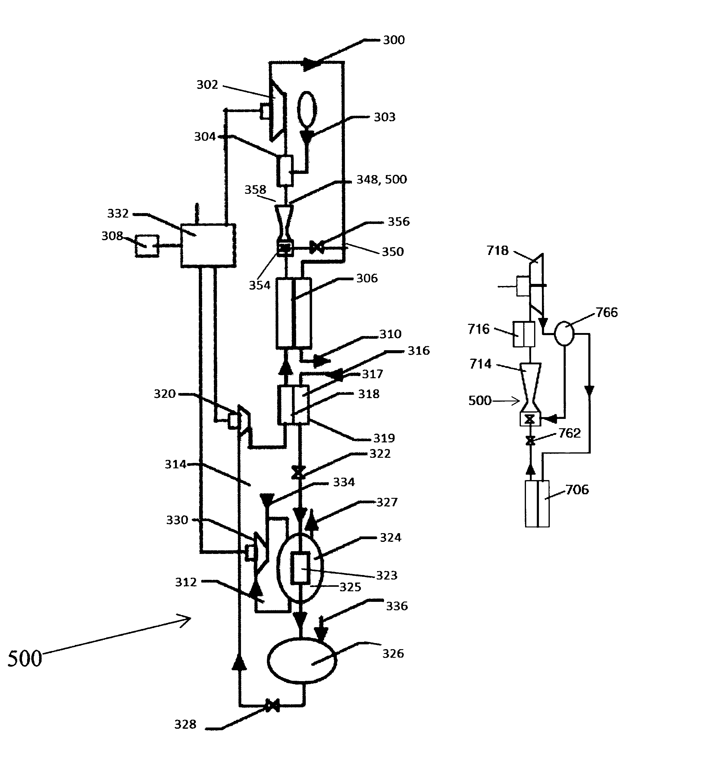
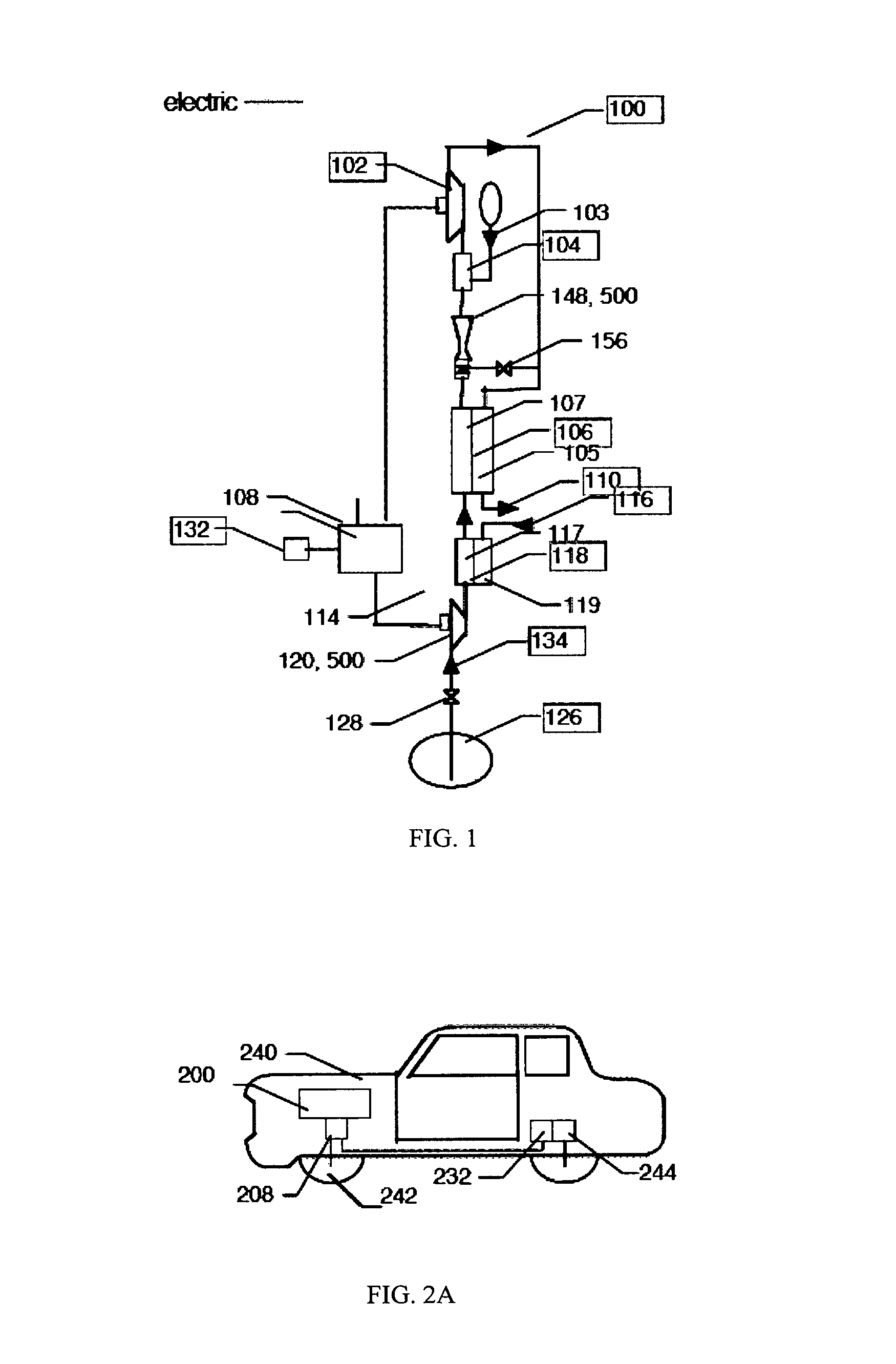
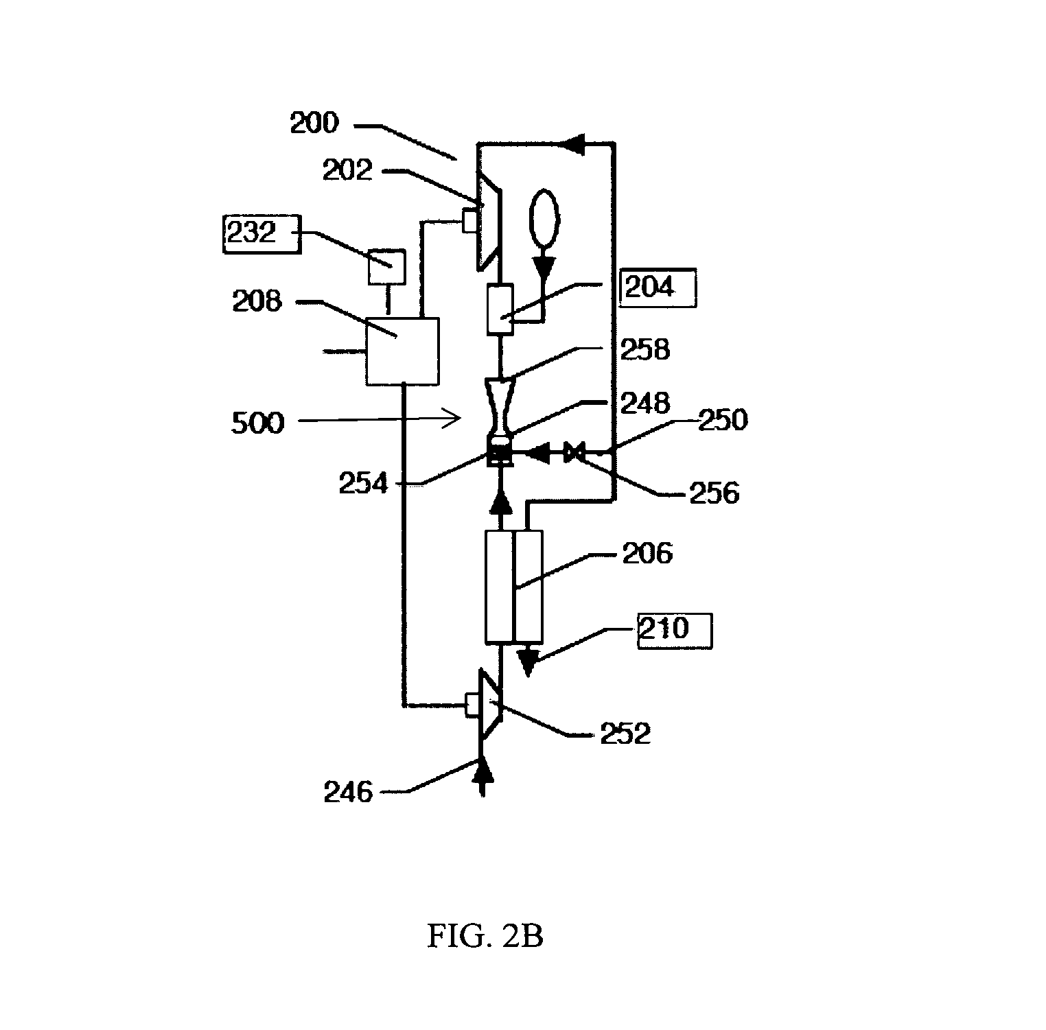
[0033]Referring first to FIG. 1, a schematic illustrating a preferred embodiment of a gas turbine 100 of the present invention is provided. Gas turbine 100 circulates a working fluid and creates energy through the various heating, cooling, and compression of the working fluid. The working fluid is preferably air, but may also be nitrogen, nitric oxide, argon, or neon. Gas turbine 100 includes at least turbine-generator 102, air heater 104, recuperator 106, and working fluid compression means 500. Working fluid compression means 500 are means for compressing and cooling the working fluid and supplying the compressed working fluid to air heater 104. Several embodiments of working fluid compression means 500 are identified herein. In some embodiments of working fluid compression means 500, the means supply the compressed working fluid to air heater 104 directly. In other embodiments of working fluid compression means 500, there are intermediary gas turbine features through which the wo...


PUM


Abstract

The present invention is a prime mover with recovered energy driven compression for stationary and motor vehicle application. Efficient low compression operation, especially beneficial to small gas turbines, is enabled with either ambient or cryogenic intake air. Recovered energy, liquefied air cooling and re-liquefaction of air by a cryogenic sink minimize motive fluid compression work of a jet compressor driving exhaust gas recirculation. Regenerative heat exchanger terminal temperature difference relative to turbine temperature drop and heat exchanger surface area are reduced.

Description

CLAIM OF PRIORITY[0001]This application is a continuation in part and claims the benefit of priority of co-pending U.S. patent application Ser. No. 13 / 374,861, filed on Jan. 20, 2012.FIELD OF THE INVENTION[0002]The present invention relates to the use of recovered energy to provide minimal compression work in low compression motor vehicle and stationary engines, and in particular to systems for exhaust gas recirculation by a jet compressor driven by motive fluid, which may be compressed by recovered energy, cooled by liquefied air and re-liquefied by a cryogenic sink to minimize motive compression work.BACKGROUND[0003]A high efficiency prime mover with renewable energy storage has long been a goal of motor vehicle and stationary engine design to provide energy independence, conserve fossil fuels, and reduce emission of combustion products. While the expansion engine of the present invention is applicable to both reciprocating and rotary engines, it is especially beneficial to the ga...

Claims


Application Information

Patent Timeline
Patent Type & Authority Patents(United States)
IPC IPC(8): F02C7/08F02C1/04F02C6/20F02C7/10F02C3/34F02C6/18F02C7/18F02C6/16
CPCF02C7/10F02C1/04F02C3/34F02C6/16F02C6/18F02C6/20F02C7/08F02C7/185F05D2250/82F05D2260/601Y02E60/16
Inventor KAUFMAN, JAY STEPHEN
Owner KAUFMAN JAY STEPHEN
Why Eureka
Try Eureka