
Optical wavelength converter and illumination system with same

a technology of optical wavelength converter and illumination system, which is applied in the direction of instruments, lighting and heating apparatus, semiconductor devices for light sources, etc., can solve the problems of reducing the wavelength conversion efficiency of phosphor powder, high optical power of laser light for exciting phosphor powder, and high heat content of the substrate of the conventional transmission-type optical wavelength converter, so as to achieve uniform and stably transmitted, effective and precise control

Active Publication Date: 2018-12-18
DELTA ELECTRONICS INC
View PDF20 Cites 3 Cited by
  • Summary
  • Abstract
  • Description
  • Claims
  • Application Information

AI Technical Summary

Benefits of technology

[0009]The present invention provides an optical wavelength converter and an illumination system with the optical wavelength converter. Due to the arrangement of a second substrate, the laser speckle can be uniformly and stably transmitted through the optical wavelength converter, and the balanced rotation of the optical wavelength converter can be effectively achieved. Consequently, the optical wavelength converter may be effectively and precisely controlled, and the unmatching of the blue speckle will be minimized. Under this circumstance, the intensity and the chroma of the output light are more stable, and the quality of the output light is enhanced.
[0010]The present invention provides an optical wavelength converter and an illumination system with the optical wavelength converter. Since the first segments of the first substrate and the second segments of the second substrate are alternately arranged, the balanced rotation of the optical wavelength converter is optimized. Consequently, the problem of causing deviation or vibration of the optical wavelength converter is overcome, and the light output is more stable.

Problems solved by technology

However, with the increasing demands on the luminance of the projector, the optical power of the laser light for exciting the phosphor powder is high.
Consequently, the substrate of the conventional transmission-type optical wavelength converter is very hot.
Under this circumstance, the wavelength conversion efficiency of the phosphor powder is reduced, and thus the overall output light is adversely affected.
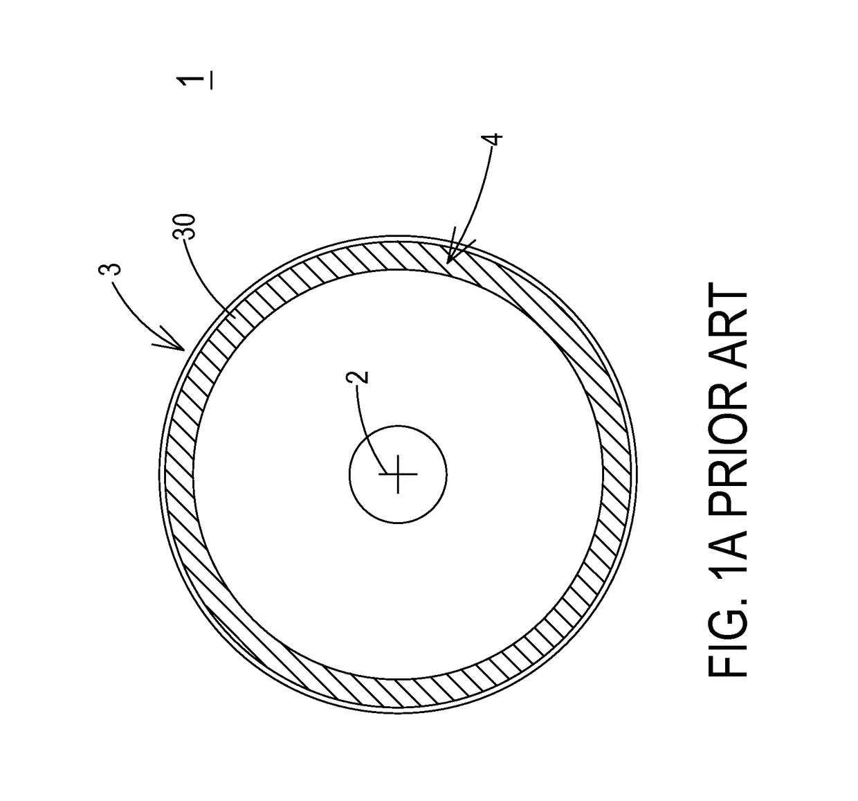
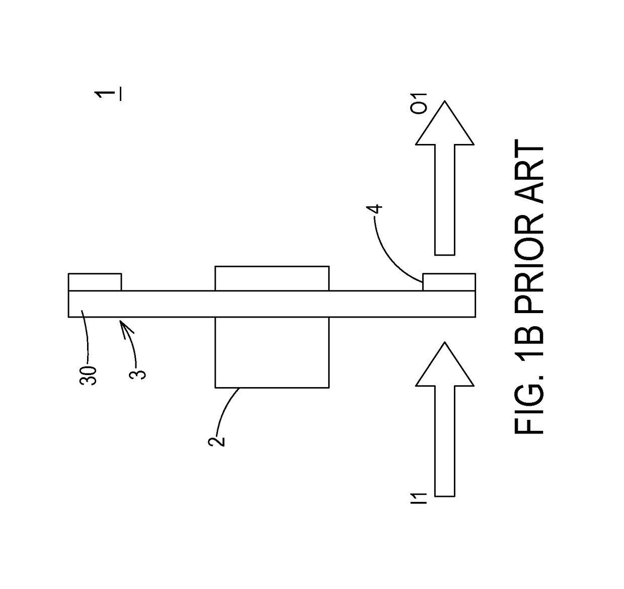
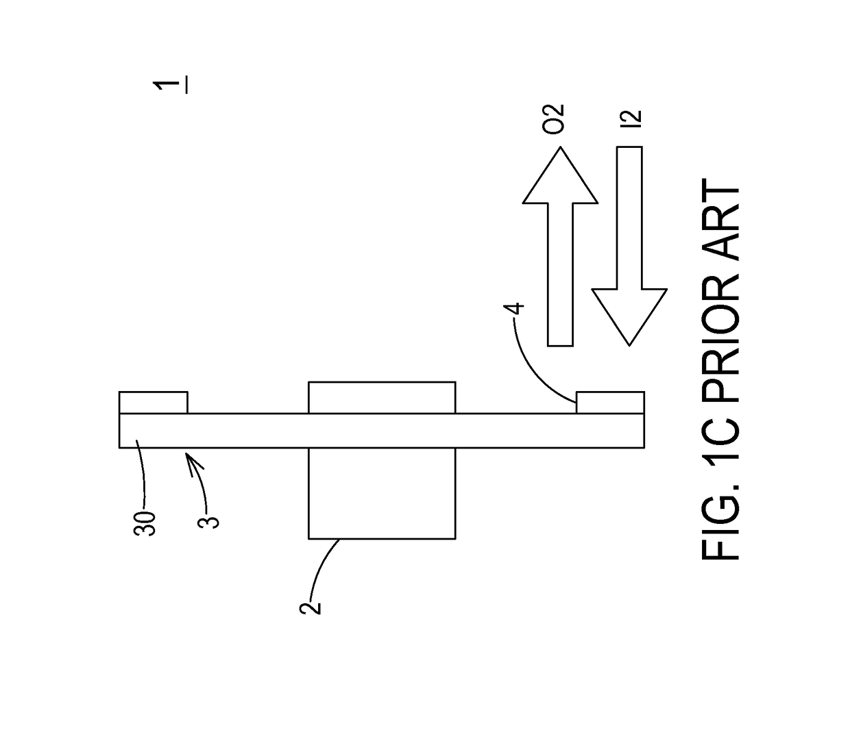
However, since the rotation of the optical wavelength converter 1 is driven by the motor 2, it is difficult to control the oscillation amount of the motor 2 under high rotation rate.
Under this circumstance, the intensity and the chroma of the output light are not stable, and the quality of the output light is deteriorated.

Method used


Image

  • Optical wavelength converter and illumination system with same
  • Optical wavelength converter and illumination system with same
  • Optical wavelength converter and illumination system with same

Examples


Embodiment Construction

[0027]The present invention will now be described more specifically with reference to the following embodiments. It is to be noted that the following descriptions of preferred embodiments of this invention are presented herein for purpose of illustration and description only. It is not intended to be exhaustive or to be limited to the precise form disclosed.

[0028]FIG. 3A schematically illustrates the structure of an optical wavelength converter according to a first embodiment of the present invention. FIG. 3B schematically illustrates the architecture of an illumination system with the optical wavelength converter of FIG. 3A. The optical wavelength converter 5 is applied to the illumination system 6. The illumination system 6 has a solid-state light-emitting element 61 for emitting a first waveband light L1. An example of the optical wavelength converter 5 includes but is not limited to a phosphor wheel. In this embodiment, the optical wavelength converter 5 comprises a first substr...


PUM


Abstract

An optical wavelength converter includes a first substrate, a first wavelength conversion material, and a second substrate. The first substrate has at least one first segment. The first wavelength conversion material is contained in the first segment for converting a first waveband light into a second waveband light. The second waveband light is reflected by the first segment. The second substrate is arranged beside the first substrate, and has at least one second segment. The first waveband light is transmitted through the second segment.

Description

FIELD OF THE INVENTION[0001]The present invention relates to an optical wavelength converter, and more particularly to an optical wavelength converter for providing a stable and high-quality light source. The present invention relates to an illumination system with the optical wavelength converter.BACKGROUND OF THE INVENTION[0002]An optical wavelength converter is an optical transducer that converts a light having a first wavelength into a color light having a second wavelength. Generally, the optical wavelength converter is applied to a spotlight, a car headlight, a monitor, a projector or other special illumination circumstances.[0003]Conventionally, the optical wavelength converter has a phosphor wheel. When a laser light source emits a laser beam to excite a phosphor powder of the phosphor wheel, a color light with a different wavelength is produced. Moreover, as the phosphor wheel is driven to rotate by a motor, different color lights are sequentially produced according to a ti...

Claims


Application Information

Patent Timeline
Patent Type & Authority Patents(United States)
IPC IPC(8): F21V9/40F21S10/00F21V9/30G02B27/14G02B27/10G03B33/08G03B21/20G02B26/00F21Y115/10F21Y115/30
CPCG02B27/141F21S10/007F21V9/30G02B27/1006G03B33/08G03B21/204G02B26/008F21Y2115/10F21Y2115/30F21V9/38F21V9/45F21V13/08
Inventor CHANG, KEH-SUCHOU, YEN-ICHEN, CHILIU, MENG-HANCHEN, JAU-SHIU
Owner DELTA ELECTRONICS INC
Learn More