
Liquid spraying head of plant protection unmanned aerial vehicle

A technology for planting and protecting drones and spray heads, applied in aircraft parts, spray devices, liquid spray devices, etc., can solve the problems of uneven spraying area and low service life, and achieve the effect of increasing spraying area

Inactive Publication Date: 2021-02-19
湖北山石智能科技有限公司
View PDF14 Cites 0 Cited by
  • Summary
  • Abstract
  • Description
  • Claims
  • Application Information

AI Technical Summary

Problems solved by technology

[0003] The spray head installed on the plant protection UAV requires stable working efficiency and uniform spraying work to ensure efficient spraying work. The existing spray head is not significantly different from the ordinary spray head on the market, and its service life is high under high-intensity work requirements. It is relatively low, and the spraying area is uneven when spraying from high to downward. Therefore, it is necessary to invent a spray head for plant protection drones

Method used


Image

  • Liquid spraying head of plant protection unmanned aerial vehicle
  • Liquid spraying head of plant protection unmanned aerial vehicle
  • Liquid spraying head of plant protection unmanned aerial vehicle

Examples


Embodiment 1

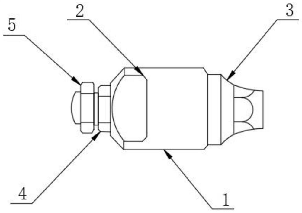
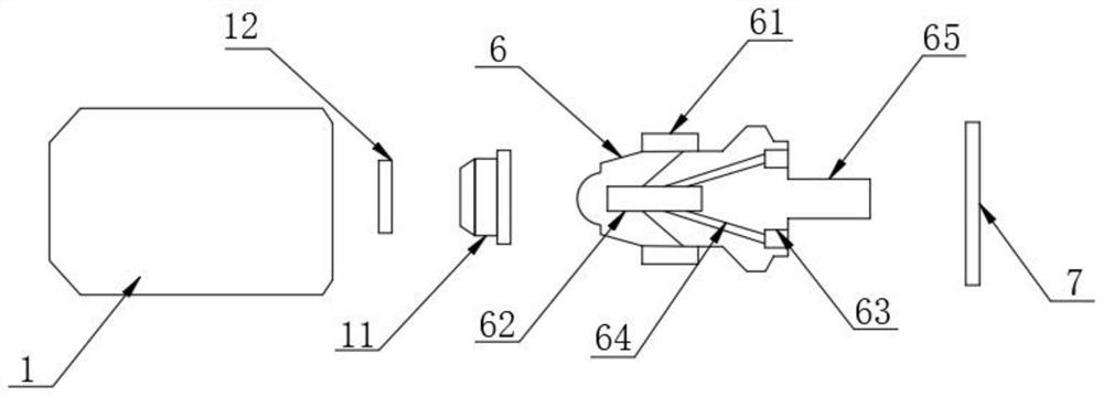
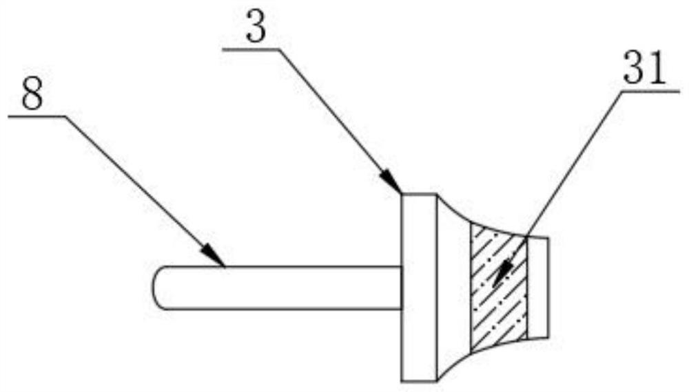
[0022] Such as Figure 1-4 The liquid spray head of a plant protection drone shown includes a liquid spray housing 1, the front surface of the liquid spray housing 1 is provided with a mounting seat 2, and one end of the liquid spray housing 1 is threadedly connected with a nozzle tail shell 3, and the spray head tail shell 3 is threaded. The other end of the liquid housing 1 is connected with a nozzle connector 4, and one side of the nozzle connector 4 is threaded with a liquid outlet 5. The liquid spray housing 1 is provided with a liquid cap 6, and the top and bottom of the liquid cap 6 are provided with reinforcements. The block 61 and the reinforcing block 61 are fixedly arranged on the top and bottom of the inner wall of the liquid spray housing 1, a mixing chamber 62 is provided inside the liquid cap 6, a sealing gasket 7 is provided on one side of the liquid cap 6, and a sealing gasket 7 is provided on the inner side of the nozzle tail case 3. Infusion tube8.

[0023]...

Embodiment 2

[0028] One side of the inner wall of the liquid cap 6 is provided with an air valve 63, the air valve 63 is arranged on the top and bottom of the infusion tube 8 and the inside of the air valve 63 is provided with a vent pipe 64, the vent pipe 64 communicates with the mixing chamber 62, and the air valve 63 is connected to the air pump on the outside After the air is transported into the mixing chamber 62 to mix with the liquid medicine, the high-pressure gas drives the liquid medicine to spray out to the outside, and the liquid medicine and gas are uniformly and stably transmitted.

[0029] One end of the liquid cap 6 is provided with a slot 65, the infusion tube 8 is plugged into the slot 65, and the sealing gasket 7 is arranged around the outside of the slot 65, and the sealing gasket 7 ensures that the internal medicinal liquid does not leak.

[0030] The specific real-time method of this embodiment: the medicinal liquid enters the slot 65 through the infusion tube 8, the s...


PUM


Abstract

The invention relates to a liquid spraying head of a plant protection unmanned aerial vehicle. The liquid spraying head comprises a liquid spraying shell, wherein a mounting base is arranged on the surface of the front side of the liquid spraying shell, one end of the liquid spraying shell is in threaded connection with a spraying head tail shell, the other end of the liquid spraying shell is communicated with a spraying head connector, and a liquid outlet is formed in one side of the spraying head connector in a threaded manner; and a liquid cap is arranged in the liquid spraying shell, reinforcing blocks are arranged at the top and the bottom of the liquid cap, and the reinforcing blocks are fixedly arranged at the top and the bottom of the inner wall of the liquid spraying shell. According to the liquid spraying head, by arranging the spray head tail shell, the liquid outlet and a liquid conveying pipe, liquid medicine enters the spray head tail shell from the outer side of the spray head tail shell, is filtered through a filter screen and then enters the liquid conveying pipe, then the liquid medicine is led into the liquid cap to be mixed and conveyed with gas, the mixed gas and liquid are sprayed out from the liquid outlet, liquid is sprayed out through liquid passing openings in the surfaces of movable fan blades and gaps between the movable fan blades, and meanwhile, the movable fan blades can rotate on the inner wall of the liquid outlet, so that the liquid medicine is evenly sprayed to increase the spraying area.

Description

technical field [0001] The invention relates to the technical field of plant protection drones, in particular to a liquid spray head of plant protection drones. Background technique [0002] The plant protection drone is small in size but powerful in function. It can carry 8-10 kilograms of pesticides, spray pesticides at low altitude, and can complete the operation of one mu of land per minute. Its spraying efficiency is 30 times that of traditional manual labor. The aircraft adopts intelligent control, and the operator controls it through the ground remote control and GPS positioning. The downward airflow generated by the rotor helps to increase the penetration of the fog flow on the crops, and the control effect is good. At the same time, the pesticide application is controlled remotely. Greatly improved the safety of pesticide spraying. It can also carry out real-time monitoring of agricultural diseases and insect pests by carrying video devices. [0003] The spray he...

Claims


Application Information

Patent Timeline
Patent Type & Authority Applications(China)
IPC IPC(8): B05B7/04B64D1/18
CPCB05B7/0416B05B7/0441B64D1/18
Inventor 陶蕾芳杨顺恒
Owner 湖北山石智能科技有限公司
Learn More