Projector Lights

Active Publication Date: 2018-12-18
SEASONAL SPECIALTIES
View PDF6 Cites 8 Cited by
  • Summary
  • Abstract
  • Description
  • Claims
  • Application Information

AI Technical Summary

Benefits of technology

[0005]The disclosure further includes each of said heads being positioned to point to substantially the same target and wherein the heads are sequentially activated to project different images, resulting in a visual effect of a moving image.
[0006]The disc

Problems solved by technology

Ornamental lighting, particularly outdoor lighting is generally difficult to install and use a considerable amount of energy.
Often th

Method used


Image

  • Projector Lights
  • Projector Lights
  • Projector Lights

Examples


Embodiment Construction

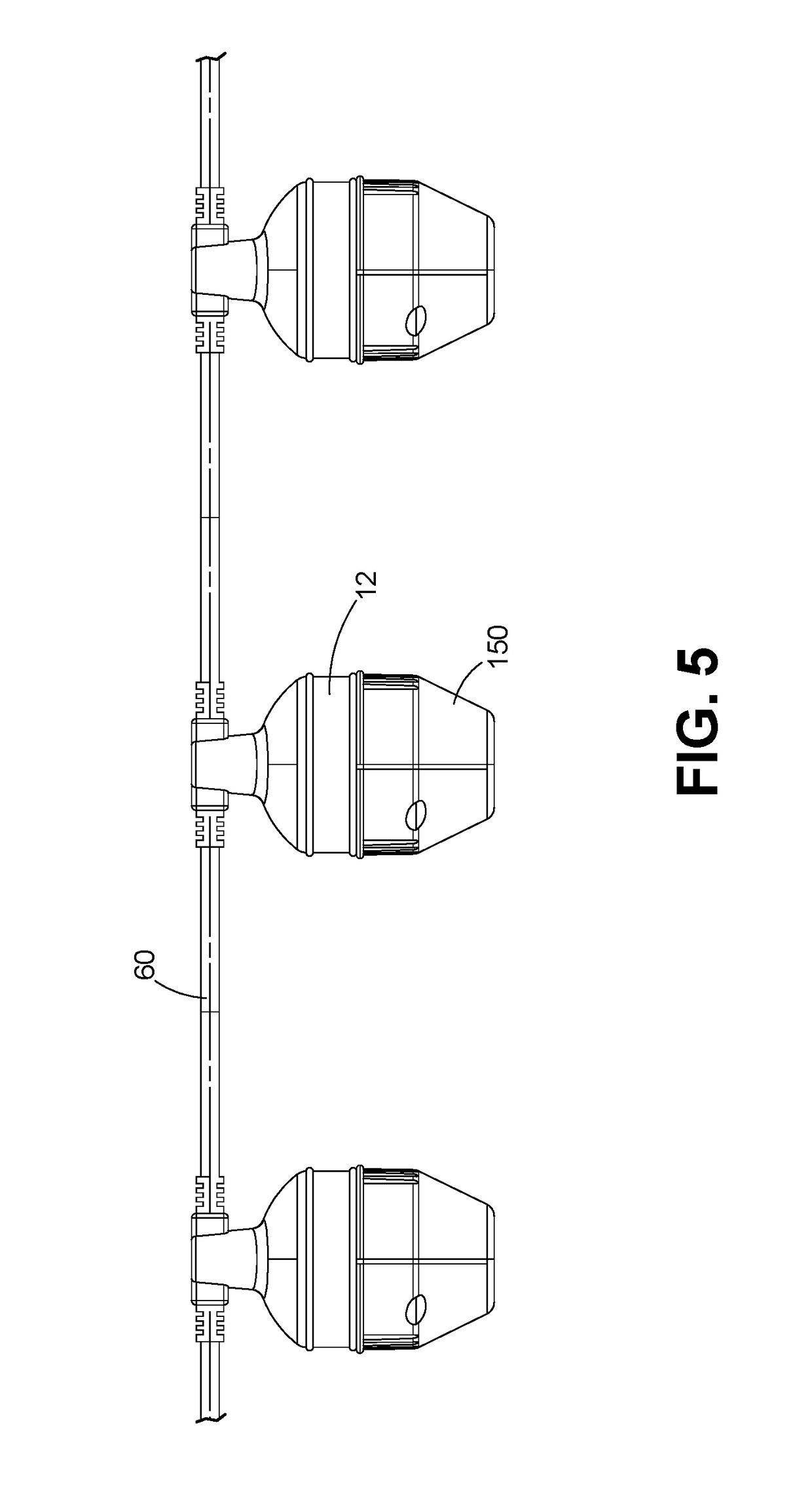
[0040]This disclosure describes a single light projector, and a system of projector lamps, a control system and a method of making or operating same, in various related embodiments.

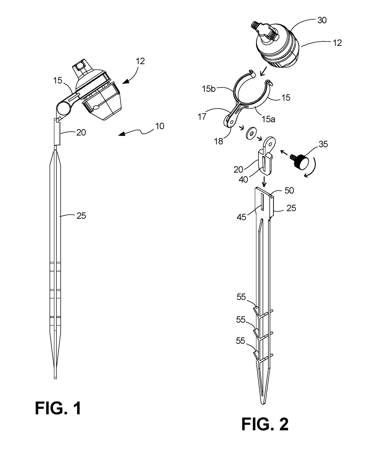
[0041]FIGS. 1 and 2 illustrates an assembled light projector 10, with a projector head 12, a yoke 15, an articulating flange 20, which is optionally inserted into a ground stake 25, when used outdoors to mount the projector to the ground.

[0042]Yoke 15 includes a pair of resiliently biased arms 15a / 15b which resiliently expands to receive a recess 30 on head 12 to make the head removable against the bias force. An extension 17 extends from the arms 15a / b and includes a planar portion 18 with an aperture for receiving a set screw / bolt 35. A like aperture on flange 20 allows bolt 35 to pass through both members and be tightened against a nut to releasably lock the flange and yoke together at a user selectable angle which set the projection angle for the head 12.

[0043]Flange element 20 includes a progressivel...


PUM


Abstract

A projection light source system and method of manufacture are shown in various embodiments. In one embodiment a single projector head (12) includes a light source (95) which projects through a condenser lens (90) and then an image transparency 120 which may be film or other digital media, and through an imaging lens 140 which is adjustable by rotation of a threaded cap 150. Adjustment of the image target location is achieved in part via an adjustment in the flange (20) which is rotatably connected to the head. Sequencing of images from a plurality of heads which are internally, remotely or IP controllable creates the ability project a succession of fixed images from a succession of heads either overlapping their target point or adjacent to create the effect of motion.

Description

FIELD OF THE DISCLOSURE[0001]The present invention is directed to ornamental lighting, more specifically lighting used to project an image.BACKGROUND[0002]Ornamental lighting, particularly outdoor lighting is generally difficult to install and use a considerable amount of energy. Often the climatic conditions are not favorable and there is danger in installing strings of lights on tall structures which require a ladder. A solution is needed which eliminates the drawbacks of prior art string lights which are easy to install but provide engaging imagery while providing energy savings.BRIEF SUMMARY[0003]To assist the reader in preparing to digest the detailed description and claims below, a short summary has been provided. It is far from complete and only provides a glimpse of the invention concepts. It is not intended to define the scope of the invention. The claims perform that function.[0004]The present disclosure shows projector light or light system, in the case of a string of pro...

Claims


Application Information

Patent Timeline
IPC IPC(8): G03B21/20F21V21/08G03B33/08F21V21/00G03B21/14F21S4/10
CPCF21V21/0824F21V21/14F21W2131/10G03B21/001G03B21/2033F21S4/10G03B21/142G03B21/145G03B21/20G03B21/2053G03B33/08
Inventor ALTAMURA, STEVEN J.
Owner SEASONAL SPECIALTIES
Why Eureka
Try Eureka