Imaging and analyzing parameters of small moving objects such as cells

a technology of moving objects and parameters, applied in the field of imaging moving objects or particles, can solve the problems of inability to simplify protocols, little or no fetal cells for analysis, and the number of biological and medical applications that are currently impractical, and achieve the effects of increasing the amount of light incident upon objects, prolonging imaging, and long integration tim

Inactive Publication Date: 2002-06-13
CYTEK BIOSCI
View PDF0 Cites 121 Cited by
  • Summary
  • Abstract
  • Description
  • Claims
  • Application Information

AI Technical Summary

Benefits of technology

[0018] The present invention provides a method and apparatus utilizing multiple detectors to determine at least one characteristic of an object moving through a field a view, relative to the detectors. Preferably the detectors are stationary, although it should be understood that a critical aspect is that there be relative motion between the object and the detectors, thus the present invention anticipates embodiments in which the object is stationary and the detectors are in motion. It should be noted that the data provided by the present invention include simultaneous spatial and spectral images covering a large bandwidth at high resolution, and further that the present invention preserves the spatial origin of the spectral information gathered from the object. In particular, the use of multiple detectors ensures no distortion or convolution of the image occurs due to the emission bandwidth, and as a result, a deconvolution is not needed to correct the image. Sufficient detectors are employed to provide separate detectors for each spectrally decomposed image.
[0021] As a result of light collimation by the collection lens in this embodiment, all light emitted from a first point in the object travels in parallel rays. Light emitted from a second point in the object will also travel in parallel rays, but at a different angle relative to light from the first point. In this manner, spatial information in the object is transformed by the collection lens into angular information in the collection path. The plurality of different reflecting elements each reflect different characteristics of light, thereby acting on the collimated light such that different spectral components leave the plurality of different reflecting elements in different directions, preferably in a plane substantially orthogonal to the direction of the movement between the object and the imaging system. In this manner, both spatial and spectral information in the object are transformed into angular information. The at least one imaging lens acts on the collimated light to transform different light angles into different positions on each detector. Spatial information is preserved by the system since light from the different positions in the object is projected to different positions on the detector, for both axes. In addition, preferably light of different spectral composition that originates from the object is projected onto different detectors, in an axis substantially orthogonal to the movement. In this manner, the spatial information from the object is preserved, while spectral information covering a large bandwidth is simultaneously collected at high resolution. The use of a single detector for each different spectral component means that each detector can be focused independently for each color, thereby simplifying the optical design by eliminating the constraint of longitudinal color correction required for single detector systems. A still further advantage is that the quantum efficiency of each detector can be individually optimized for its particular color band, thereby increasing the overall sensitivity of the system.
[0026] Particularly in embodiments employing a single lens, optical distortions are increased after light passes through each dichroic reflecting element. In one embodiment, such distortions are reduced by employing cube substrates wherein a numerical aperture associated with each cube substrate is sufficiently small so as to substantially eliminate coma and astigmatism. In other embodiments, a correction plate is disposed between each successive light reflecting element, each correction plate being oriented relative to an immediately preceding light reflective element such that any astigmatism imparted by the immediately preceding light reflective element is substantially eliminated. Preferably the orientation of the correction plate is substantially orthogonal relative to an axis about which the immediately preceding light reflective element is rotated to direct reflected light toward one of the plurality of detectors.
[0029] It should be noted that the use of a TDI detector in the present invention results in an extended imaging region along the axis of motion and a correspondingly long integration time. Several light sources can be simultaneously projected into the imaging region, increasing the amount of light incident upon objects therein. In addition, the combination of an extended imaging region and the orthogonal orientation of the spectral dispersion axis relative to the axis of the motion allows multiple objects to be imaged simultaneously. The long integration time and parallel image acquisition of this embodiment allows sensitive and consistent imaging performance to be combined with high throughput.

Problems solved by technology

There are a number of biological and medical applications that are currently impractical due to limitations in cell and particle analysis technology.
These protocols often yield little or no fetal cells for analysis, because a fraction of the fetal cells are lost at each step of the protocol.
Nevertheless, the protocols cannot be simplified because of limitations in existing analysis technology.
This ideal is not possible with conventional systems, because conventional cell sorters lack the necessary imaging abilities, sensitivity, and repeatability to reliably identify fetal cells and enumerate the number and color of FISH probes used to make the diagnosis.
The combination of low fetal cell yields and lengthy processing times precludes the clinical application of non-invasive fetal testing with existing technology.
In the prior art, there have been advances that might be applied to these applications, but significant limitations still remain.
However, this approach does not address the remaining principal characteristics.
In addition, the system has no spectral resolution; laser scatter and fluorescent light are collected by the imaging system indiscriminately.
Further, frame-based cameras require time to transfer data out of the camera, during which no images are acquired, and cells of interest can escape detection.
Finally, like the work of Ong et al., this patent makes no provisions for acquiring data over a large spectral bandwidth and with sufficient spectral resolution to simultaneously resolve numerous and differently colored fluorescent probes and FISH spots.
However, there is no spatial representation of the object in the system disclosed in this patent, because the object is defocussed at the detector.
Because there is no provision for re-imaging the intermediate aperture at the intensifier, the resulting signal distribution at the intensifier represents only the spectral distribution of the light and does not preserve the spatial distribution of the light from the object.
If multiple identical FISH spots are present in a cell, their spectra can be ascertained using this approach, but the number of spots cannot be determined.
Further, the short illumination height limits throughput by preventing the simultaneous imaging of multiple cells in the flow axis.

Method used


Image

  • Imaging and analyzing parameters of small moving objects such as cells
  • Imaging and analyzing parameters of small moving objects such as cells
  • Imaging and analyzing parameters of small moving objects such as cells

Examples


fifth embodiment

[0100] A sixth preferred embodiment, as illustrated in FIG. 10, is an imaging system 120 that is slightly different than the preceding fifth embodiment, since a dichroic filter 102' is employed that is angled in a different direction, toward a second TDI detector 44b. A dispersed pattern image represented by light 108' is produced by a cylindrical lens 106' in this embodiment. Just as in imaging system 100, light transmitted through dichroic filter 102' is focussed onto TDI detector 44a. Aside from using two separate TDI detectors that are disposed at different sides of the imaging system, imaging system 120 is substantially identical in operation to imaging system 100. However, just as in the third preferred embodiment, the use of two separate TDI detectors allows flexibility in the configuration of each leg of the system, including parameters such as the relative TDI readout rates, axial orientations, inclinations, focal plane positions, and magnification. It should also be noted ...

seventh embodiment

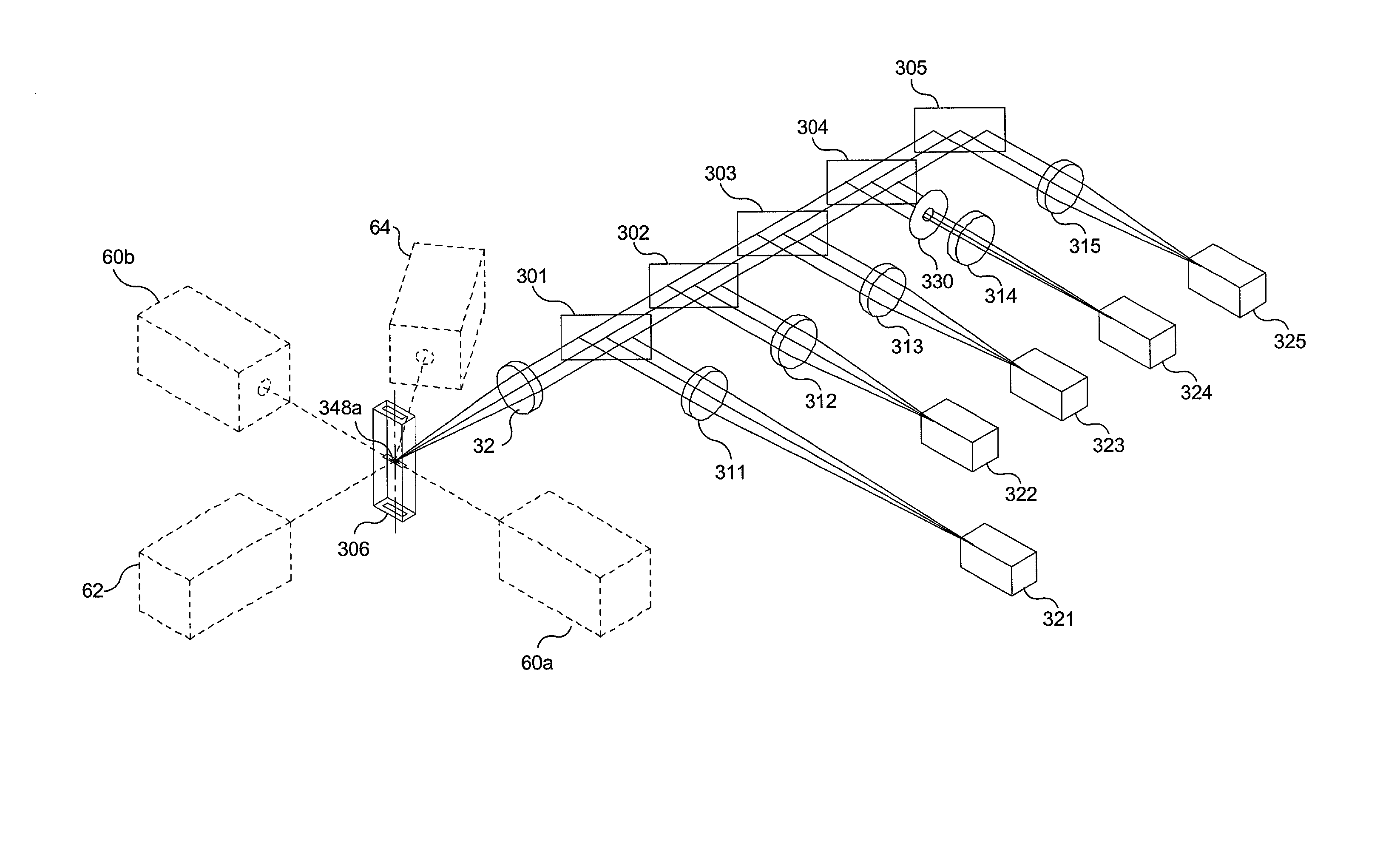
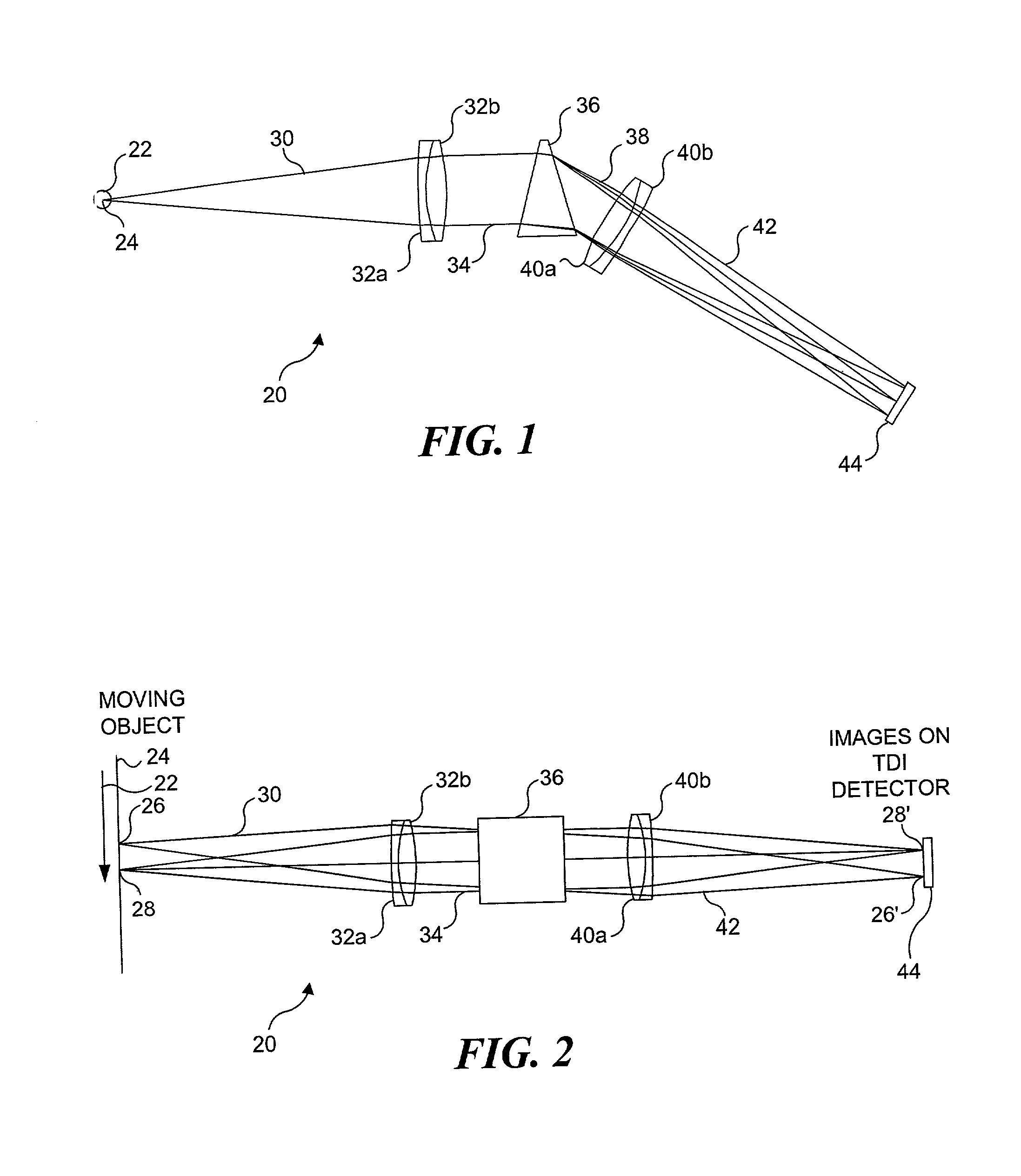
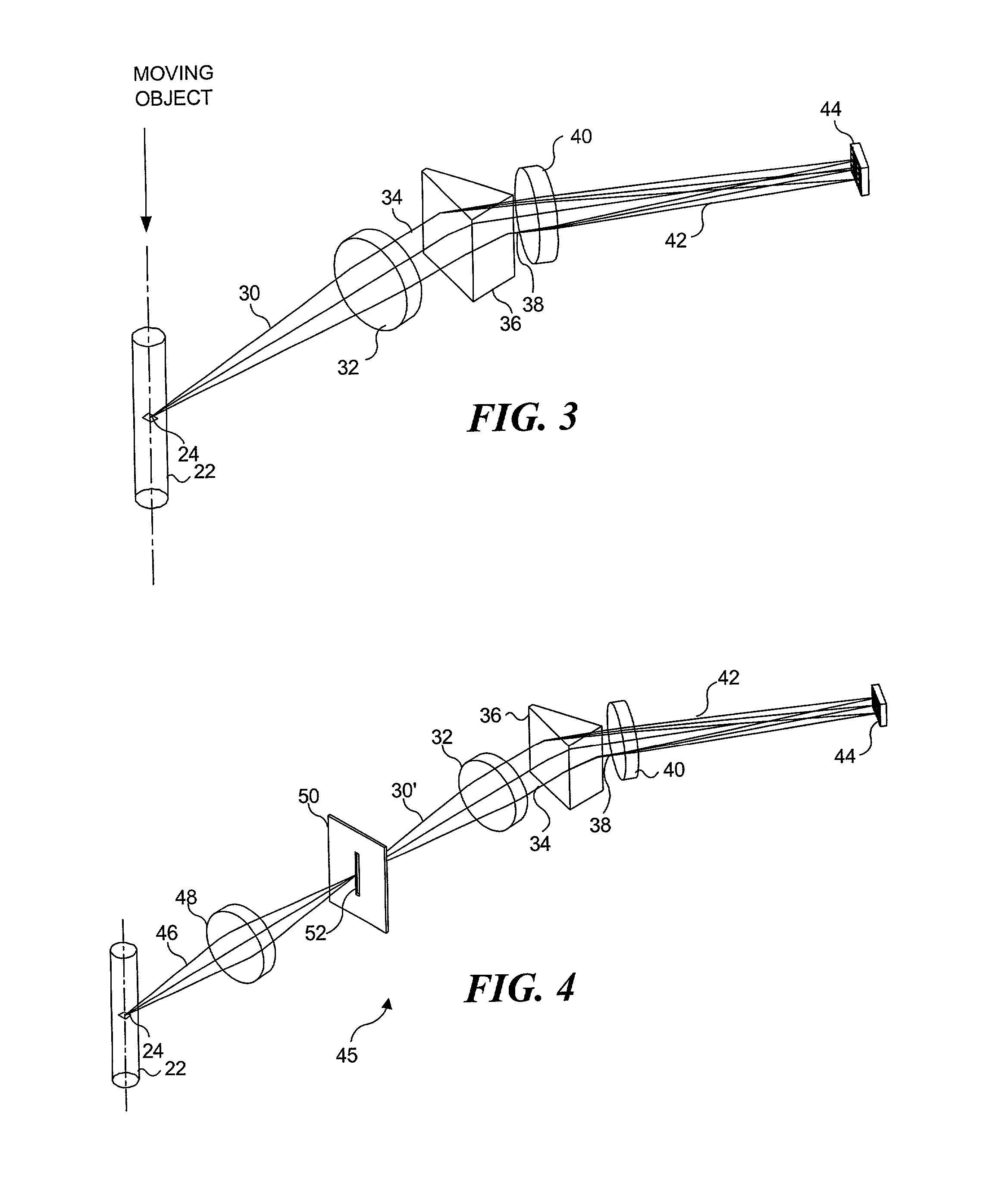
[0110] The present invention can be provided with a spectral dispersion filter assembly that does not convolve the image with the emission spectra of the light forming the image, thereby eliminating the need for deconvolution of the emission spectra from the image. FIG. 17 illustrates a seventh preferred embodiment of the invention corresponding to such a non-distorting spectral dispersion system 250 that employs a five color stacked wedge spectral dispersing filter assembly 252. This seventh embodiment is substantially similar to the embodiment shown in FIGS. 1, 2, and 3, except that spectral dispersing prism element 36 (of FIGS. 1, 2 and 3) is replaced by spectral dispersing filter assembly 252. The spectral dispersing filter assembly splits the light into a plurality of light beams having different bandwidths. Each light beam thus produced is directed at a different nominal angle so as to fall upon a different region of TDI detector 44. The nominal angular separation between each...


PUM

PropertyMeasurementUnit
angleaaaaaaaaaa
widthaaaaaaaaaa
angleaaaaaaaaaa

Abstract

Light from an object such as a cell moving through an imaging system is collected and dispersed so that it is imaged onto a plurality of separate detectors. The light is spectrally dispersed by a plurality of spaced-apart dichroic reflectors, each detector receiving light from a different one of the dichroic reflectors. Each dichroic filter reflects light of a different predefined color, passing light of other colors. The output signal from each detector is indicative of a different characteristic of the object. In one configuration, each detector is provided with a separate imaging lens. In another configuration, the detectors are spaced at varying distances from the corresponding dichroic reflectors, so that separate imaging lenses are not required.

Description

RELATED APPLICATIONS[0001] This application is a continuation-in-part application of a copending patent application Ser. No. 09 / 820,434, filed Mar. 29, 2001, which is a continuation-in-part application of patent application Ser. No. 09 / 538,604, filed on filed Mar. 29, 2000, now U.S. Pat. No. 6,211,955 issued Apr. 3, 2001, which itself is a continuation-in-part application of patent application Ser. No. 09 / 490,478, filed on Jan. 24, 2000, now U.S. Pat. No. 6,249,341 issued Jun. 19, 2001, which is a conventional application based on provisional application Serial No. 60 / 117,203, filed on Jan. 25, 1999, the benefit of the filing dates of which is hereby claimed under 35 U.S.C. .sctn. 120 and 35 U.S.C. .sctn. 119(e). The present application is also based on provisional application Serial No. 60 / 240,125, filed on filed Oct. 12, 2000, the benefit of the filing date of which is hereby claimed under 35 U.S.C. .sctn. 119(e).FIELD OF THE INVENTION[0002] This invention generally relates to ima...

Claims


Application Information

Patent Timeline
Patent Type & Authority Applications(United States)
IPC IPC(8): C07B61/00C07K1/04C12Q1/68G01J3/28G01N15/02G01N15/10G01N15/14G01N21/03G01N21/05G01N21/64G01N21/85G02B7/28G02B21/00G02B27/00G02B27/14
CPCB01J2219/00274C07K1/047G02B27/148G02B27/145C12Q1/6816G01J3/2803G01J3/2823G01N15/147G01N15/1475G01N21/031G01N21/05G01N21/6428G01N21/6456G01N21/85G01N2015/0294G01N2015/1006G01N2015/1443G01N2015/1472G01N2015/1479G01N2015/1486G01N2015/1488G01N2021/052G01N2021/058G01N2021/6417G02B7/28G02B21/00G02B27/0012G02B27/1013G02B27/126G02B27/144C12Q2563/179C12Q2563/107
Inventor ORTYN, WILLIAM E.BASIJI, DAVID A.
Owner CYTEK BIOSCI
Why Eureka
Try Eureka