Optical method and system for extended depth of focus

a technology of optical methods and depth of focus, applied in the field of imaging systems, can solve the problem that the diffractive optical element cannot achieve high efficiency

Active Publication Date: 2007-10-11
BRIEN HOLDEN VISION INST (AU)
View PDF37 Cites 115 Cited by
  • Summary
  • Abstract
  • Description
  • Claims
  • Application Information

AI Technical Summary

Benefits of technology

[0057] According to yet another aspect of the invention, there is provided an optical element for extending depth of focus of imaging, the optical element being configured as a phase-affecting, non-diffractive optical element defining a spatially low frequency phase transition, the optical element defining a predetermined pattern of phase transition regions, said transition regions being arranged in accordance with an affective aperture of a given imaging lens for which the optical element is designed, so as to provide said transition regions of the optical element within predetermined positions in the imaging lens plane, to provide periodic replication of a lateral phase shape of a light field propagating through the imaging lens with said optical element.
[0058] According to yet another aspect of the invention, there is provided an optical element for extending depth of focus of imaging, the optical element being configured as a phase-only, non-diffractive binary element defining a spatially low frequency phase transition, the optical element defining a predetermined pattern of phase transition regions, said transition regions being arranged in accordance with an affective aperture of a given imaging lens for which the o...

Problems solved by technology

It is important to note that such a high efficiency cannot be achieved by a diffractive optical ele...

Method used


Image

  • Optical method and system for extended depth of focus
  • Optical method and system for extended depth of focus
  • Optical method and system for extended depth of focus

Examples


Embodiment Construction

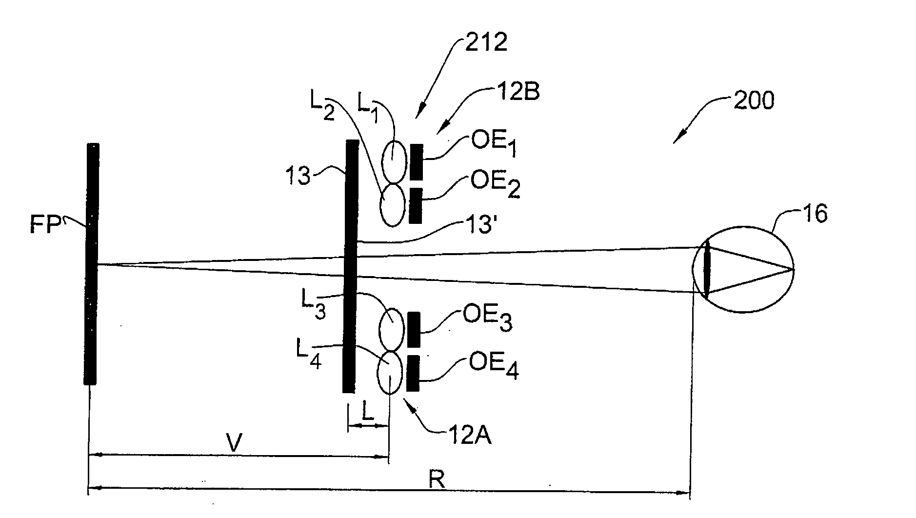
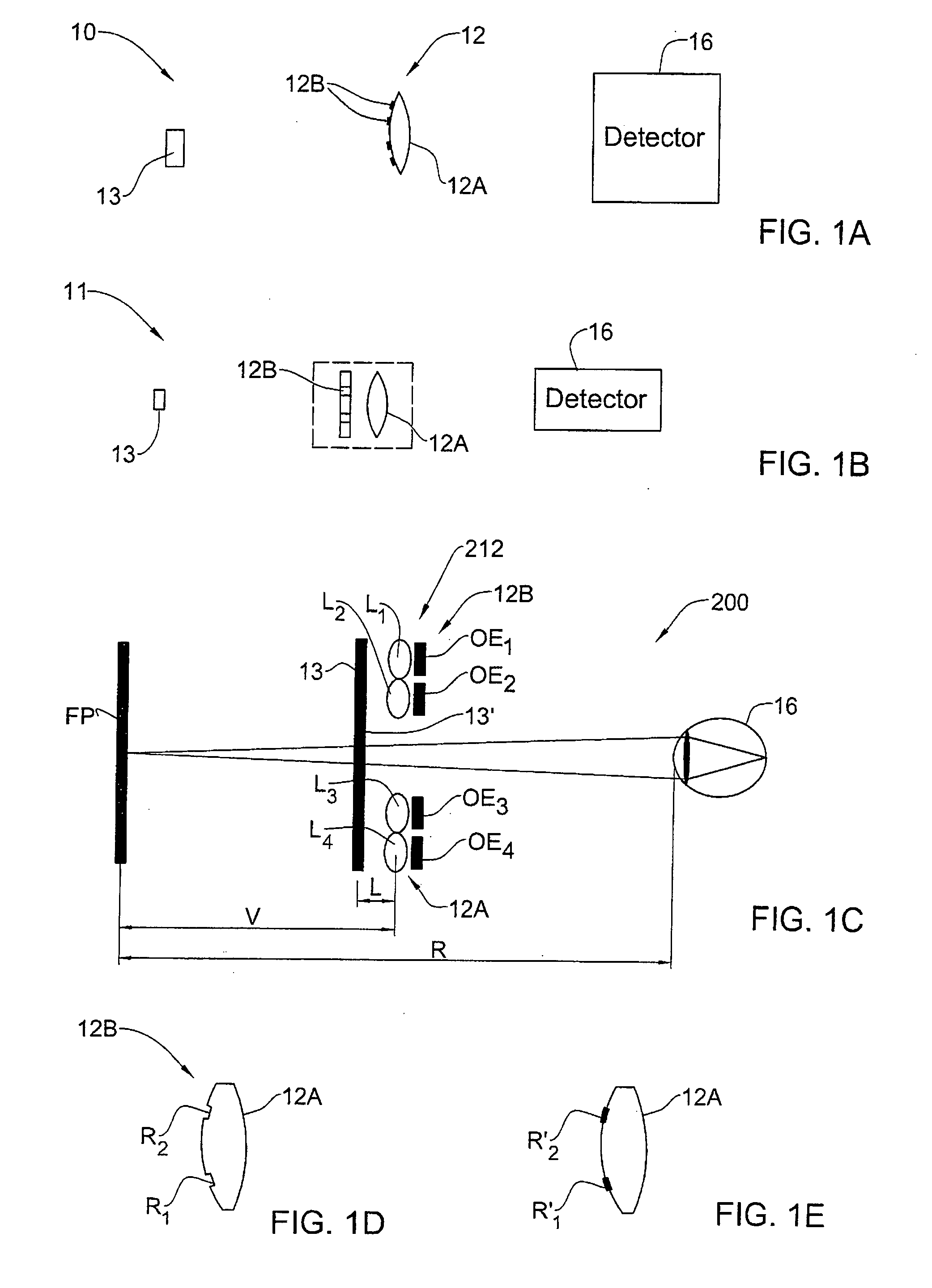
[0079] Referring to FIG. 1A, there is schematically illustrated an imaging system 10 utilizing an imaging lens arrangement 12 of the present invention. The imaging system 10 is formed by an object 13 that is to be imaged, the imaging lens arrangement 12, and a light detector unit 16. The imaging lens arrangement 12 includes a certain number of lenses 12A (generally at least one lens, single lens being shown in the present example) having a certain effective aperture D (which in the present example is the lens diameter), and a certain number of optical elements 12B (single element in the present example) associated with the lens(es) 12A. Such optical element 12B is configured and operable as an extended depth of focus (EDOF) element.

[0080] The optical element 12B is configured in accordance with the parameters of the lens 12A, i.e., its effective aperture and optionally also the optical power distribution and / or focal length. The optical element 12B is configured as a phase-affectin...


PUM


Abstract

An imaging arrangement and method for extended the depth of focus are provided. The imaging arrangement comprises an imaging lens having a certain affective aperture, and an optical element associated with said imaging lens. The optical element is configured as a phase-affecting, non-diffractive optical element defining a spatially low frequency phase transition. The optical element and the imaging lens define a predetermined pattern formed by spaced-apart substantially optically transparent features of different optical properties. Position of at least one phase transition region of the optical element within the imaging lens plane is determined by at least a dimension of said affective aperture.

Description

FIELD OF THE INVENTION [0001] This invention is generally in the field of imaging systems, and relates to an imaging lens arrangement with increased depth of focus. BACKGROUND OF THE INVENTION [0002] Extending the depth of focus of imaging systems is a very important core technology allowing its incorporation into various applications, including inter alia medically related applications where elements, such as cameras, are to be inserted into the body in order to observe and detect problematic tissues; as well as ophthalmic industry including glasses for spectacles, contact lenses, intraocular lenses or other lenses inserted surgically into the eye. The extended depth of focus solution is also needed for optical devices like microscopes or cameras for industrial, medical, surveillance or consumer applications, where focusing of light is required and where today focusing is being implemented by a multitude of lenses with the need of relative displacement between the focusing arrangem...

Claims


Application Information

Patent Timeline
IPC IPC(8): G02F1/01
CPCA61F2/16G02B27/0075G02B27/58G02C2202/22G02C7/02G02C2202/16G02B2207/129A61F2/1613A61F2/1648A61F2250/0053
Inventor ZALEVSKY, ZEEV
Owner BRIEN HOLDEN VISION INST (AU)
Why Eureka
Try Eureka