Cap, button group and method for forming button group

a button group and button technology, applied in the field of caps, can solve the problem of hard scratching on the outer surface of the cap, and achieve the effect of preventing the cap from being rotated, reducing the spring back, and cost-effectiv

Active Publication Date: 2018-12-25
YKK CORP
View PDF12 Cites 21 Cited by
  • Summary
  • Abstract
  • Description
  • Claims
  • Application Information

AI Technical Summary

Benefits of technology

[0006]The present invention is proposed in view of the above problems. Therefore, an object of the present invention is to provide a cap, a button group and a method for forming a button group, which can prevent the cap from being rotated with respect to a body, which may be induced with age, without any increase of the number of parts, and is advantageous in cost.
[0009]In an embodiment of the present invention, a Vickers hardness of the second material is harder than a Vickers hardness of the first material. Thereby, when the circumferential side of the cap is swaged to a main body of a button or a button fastener, it would possible to reduce a spring back at the swaging by the inner layer of aluminum or aluminum alloy. Further, since the outer layer is made of the material that would be harder in Vickers hardness than aluminum or aluminum alloy, the outer surface of the cap is hard to scratch. In the present invention, for example, the Vickers hardness of the first material can be set between 26 Hv or more and 95 Hv or less, and the Vickers hardness of the second material can be set between 100 Hv or more and 175 Hv or less. By using the first and second materials with those ranges of the Vickers hardness, it would be possible to provide a cap whose outer surface would be scratch-resistant.
[0015]In the present invention, the cap that is one part of a button or a button fastener comprises an inner layer made of aluminum or aluminum alloy and an outer layer made of a second material different from aluminum or aluminum alloy. The outer layer is laminated on one surface of the inner layer continuously across the bottom and the circumferential side. Thereby, it would be possible to reduce a spring back that may occur when the circumferential side of the cap is swaged, without increasing the number of parts. Therefore, it would be possible to prevent the cap from being rotated with respect to the main body. Such a rotation may occur over time. Further, since aluminum or aluminum alloy, which is cheaper than copper or copper alloy is used for a part of the cap, it would be cost effective as compared with a conventional cap made of only copper or copper alloy.

Problems solved by technology

Further, since the outer layer is made of the material that would be harder in Vickers hardness than aluminum or aluminum alloy, the outer surface of the cap is hard to scratch.

Method used


Image

  • Cap, button group and method for forming button group
  • Cap, button group and method for forming button group
  • Cap, button group and method for forming button group

Examples


Embodiment Construction

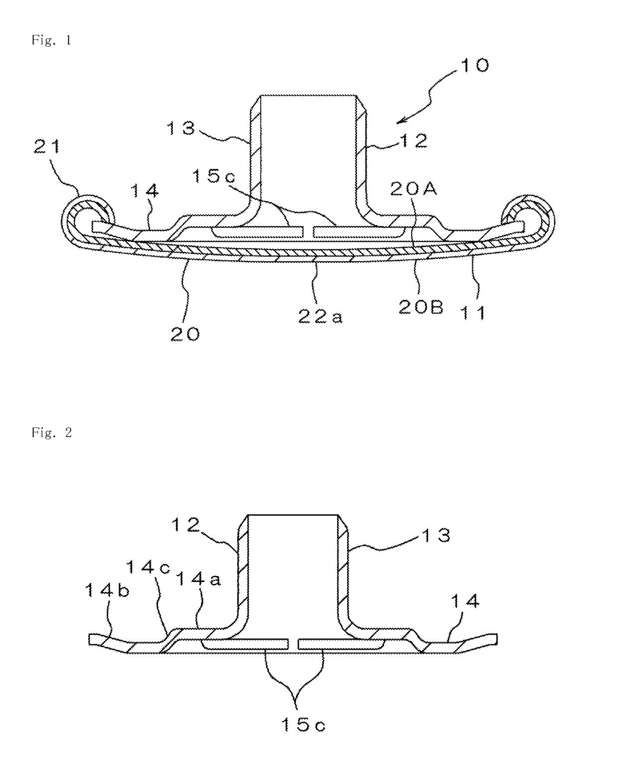
[0027]Hereinafter, preferable embodiments of the present invention will be described below with reference to the drawings. However, the present invention is not limited to those embodiments, and modifications, etc. may be made to the embodiments within the scope of the claims and a range of equivalents. FIG. 1 is a cross-sectional view that shows an embodiment of a button fastener (hereafter, merely referred to as “fastener”) 10 as one example of a button group that uses a cap 20 according to the present invention. The fastener 10 has: an approximately circular, plate-like base 11; and a cylindrical post 12 that extends upward from the base 11 (an up-and-down direction is based on FIG. 1) concentrically with the base 11. The fastener 10 is intended to attach a button such as a female snap button 30 or the like to a cloth 1 as shown in FIG. 8 by swaging the post 12 that just has penetrated through the cloth 1. The fastener 10 is composed of only two parts, namely, a fastener body 13 ...


PUM

PropertyMeasurementUnit
tensile strengthaaaaaaaaaa
thicknessaaaaaaaaaa

Abstract

There is provided a cap, which is one part of a button fastener. The cap comprises a bottom and a circumferential side rising from an edge of the bottom. The cap is composed of an inner layer made of aluminum or aluminum alloy as a first material and an outer layer made of copper or copper alloy as a second material. The first and second layer are laminated on each other continuously across the bottom and the circumferential side. A Vickers hardness of the second material may be harder than a Vickers hardness of the first material. A tensile strength of the first material may be less than 260 N / mm2, and a tensile strength of the second material may be equal to or higher than 260 N / mm2.

Description

[0001]This application is a national stage application of PCT / JP2013 / 076881, which is incorporated herein by reference.BACKGROUND OF THE INVENTION[0002]The present invention relates to a cap, a button group and a method for forming a button group, and more particularly relates to a cap, which is one part of a button or a button fastener; a button or a button as a button group with a cap, and a method for forming such a button or a button fastener.[0003]As a button or a button fastener, one type is known which includes a main body for a button or a button fastener and a cap (also referred to as a shell) which is attached to the main body. An outer surface of the cap becomes a front surface of a button or a button fastener, on which a design such as characters, logos and the like may be printed or impressed. One example of a button having such a cap is disclosed in JP,S63-22107,U, for instance. This document shows a shell member 4 as a cap in FIG. 1. Such a cap is attached to a button...

Claims


Application Information

Patent Timeline
Patent Type & Authority Patents(United States)
IPC IPC(8): A44B1/02A44B1/08A44B1/34A44B1/06A44B1/44A44B17/00
CPCA44B1/08A44B1/02A44B1/34A44B1/44A44B1/06A44B17/0088
Inventor ITO, NOBUHISA
Owner YKK CORP
Why Eureka
Try Eureka