
Method of fabricating custom dental correction device, and custom dental correction device fabricated by same

a dental correction device and custom technology, applied in dental surgery, othrodontics, medical science, etc., can solve the problems of inability to achieve successful orthodontic treatment, inability to accurately perform ideal orthodontic treatment, and difficulty in bonding brackets to exact positions of teeth, etc., to achieve accurate ideal orthodontic treatment, improve convenience and accuracy of procedure, and minimize the distance between teeth surface

Active Publication Date: 2018-12-25
IND ACADEMIC CORP FOUND YONSEI UNIV
View PDF25 Cites 2 Cited by
  • Summary
  • Abstract
  • Description
  • Claims
  • Application Information

AI Technical Summary

Benefits of technology

The present invention provides a method for fabricating a customized orthodontic appliance that can accurately perform ideal orthodontic treatment while minimizing the distance between the tooth surface and the arch wire. This appliance can also improve the convenience and accuracy of the procedure and minimize the irritating sensation in the oral cavity.

Problems solved by technology

However, since the above-described conventional orthodontic appliance includes the bracket that is mass-produced to have the predetermined shape without considering shapes of the tooth and teeth of the patient, and bonding of the bracket to the teeth of the patient and fitting to form the arch wire to the ideal dental arch shape are dependent on a competence level of an operator, the bonding of the bracket to an exact position of the tooth and the forming of the arch wire at an exact curvature are extremely difficult.
Thus, when the conventional orthodontic appliance is used, successful orthodontic treatment is not guaranteed
However, the above-described conventional orthodontic appliance has problems as follows.
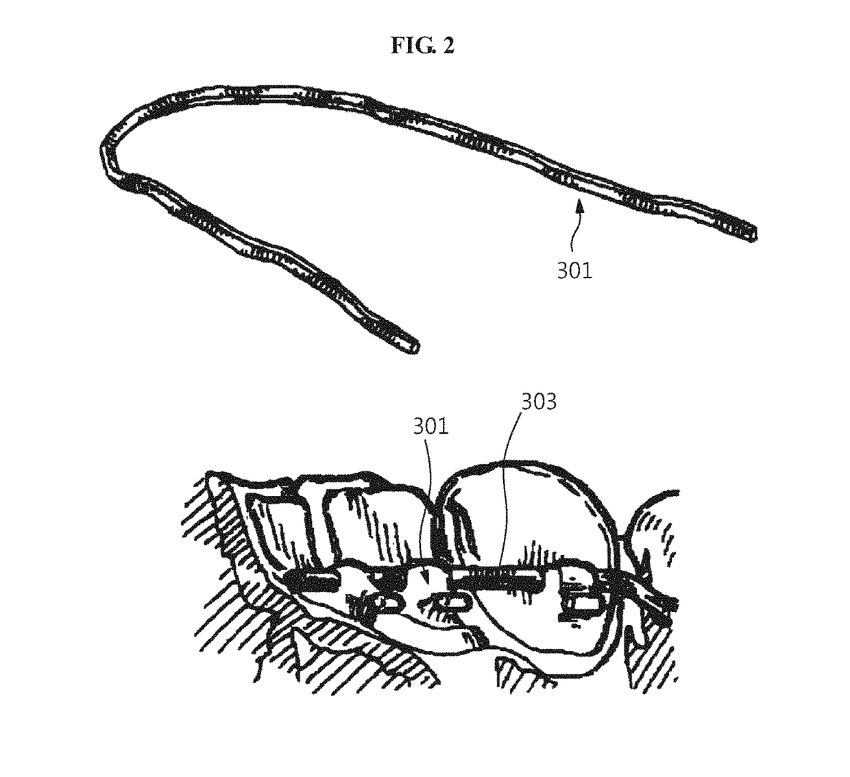
Since the orthodontic bracket, as a mass-produced stock bracket, has the linearly processed bracket slot into which the arch wire is inserted, the linearized slot may not accurately correspond to the curvature of the arch wire fabricated to fit to the dental arch after the orthodontic treatment for the patient.
In particular, the pulling force for orthodontic-treating a protruding angle of the tooth may not be provided.
This may cause a serious problem in ideal orthodontic treatment.
However, since the body portion including the bracket slot still uses a mass-produced stock product and is assembled to the base, a final bracket profile is raised and the bonding of the base at the exact position is difficult.
As described above, when the bracket profile is raised, irritation sensation increases as a volume of the orthodontic bracket increases, and a distance between the tooth surface (surface of the tooth) and the wire increases to reduce adjustability in tooth position.
As the bracket slot is spaced further away from the tooth surface (i.e., as the bracket profile is raised), the above-described problem becomes further serious.
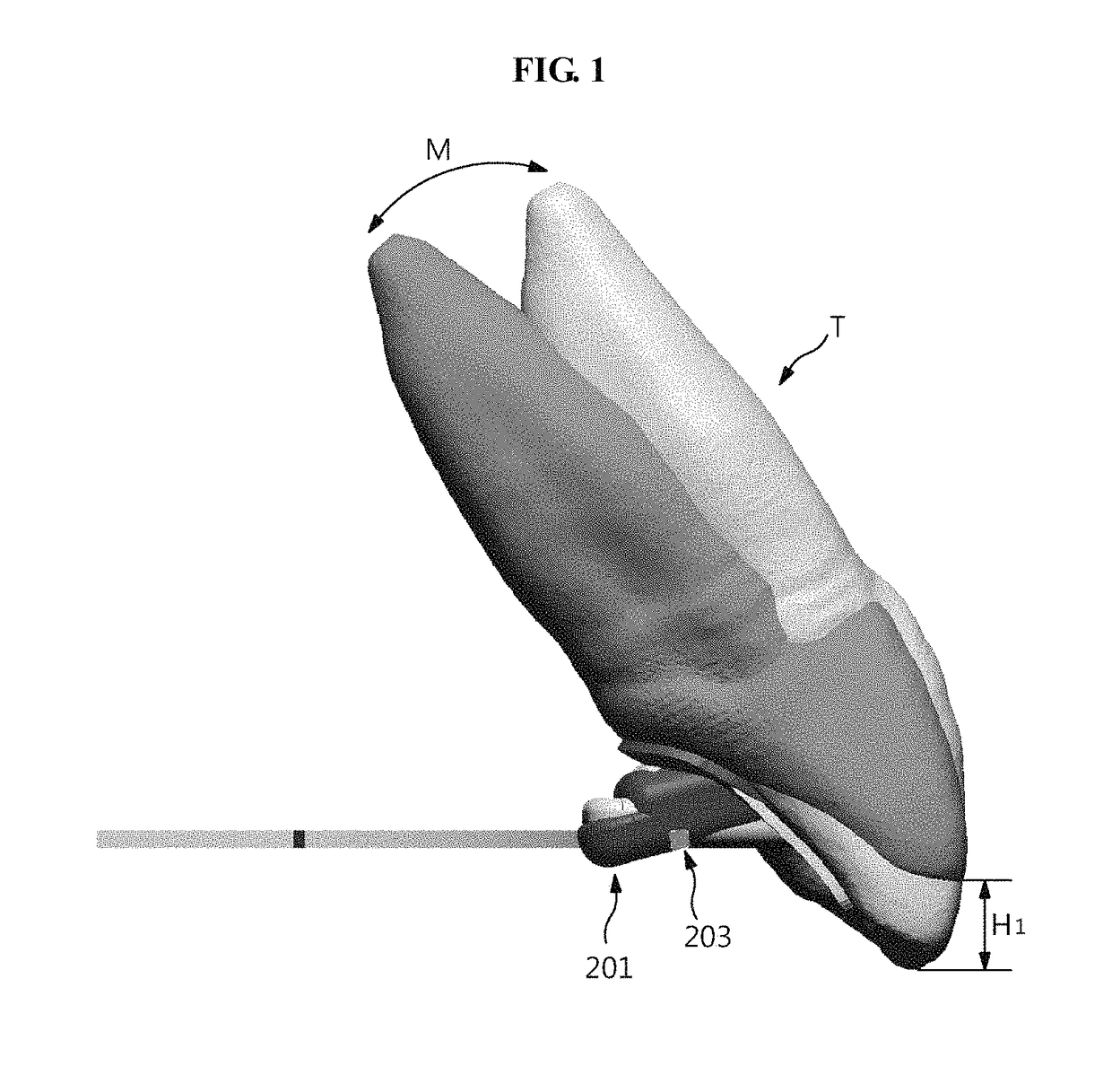
Also, when the distance from the tooth surface to the arch wire 203 increases, since the orthodontic force is applied further away from the central point or the center of resistance of the tooth T as the distance from the tooth surface or the incisal edge, which moves even when horizontal or vertical movement is performed, to the arch wire 203 increases, movement accompanied by the rotational moment instead of only horizontal or vertical movement occurs, and this rotational moment is difficult to be appropriately adjusted, thereby hardly performing the ideal orthodontic treatment.
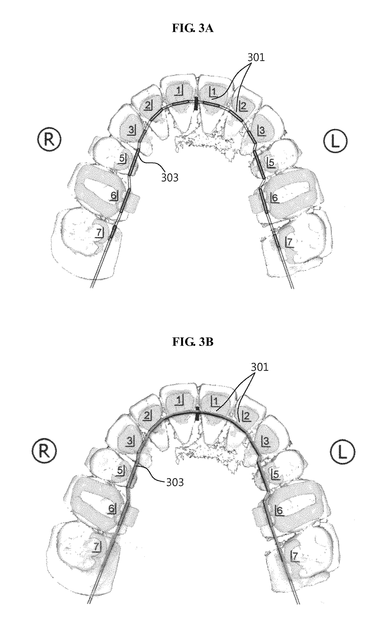
Also, in the malocclusion in a state in which a protruding tooth exists, the orthodontic bracket bonded to the tooth moves along the arch wire to straighten the protruding tooth, and when a bent portion between the linear lines is disposed in the slot, severe friction is generated on the portion, so that gliding movement of the wire in the slot becomes difficult and thus the teeth alignment is stopped or slowed.
Here, when the arch wire 303 is inserted into the bracket slot, the tooth moves to an undesired position, so that the orthodontic treatment is inaccurately performed or the bent portion is disposed in the bracket slot, thereby generating severe friction to stop or slow the tooth movement
Thus, as the arc wire 303 may not completely close-contact the bracket slot, the exact pulling force and pulling position may not be expected to hardly perform the ideal orthodontic treatment.

Method used


Image

  • Method of fabricating custom dental correction device, and custom dental correction device fabricated by same
  • Method of fabricating custom dental correction device, and custom dental correction device fabricated by same
  • Method of fabricating custom dental correction device, and custom dental correction device fabricated by same

Examples


Embodiment Construction

[0061]As illustrated in FIG. 5, a method of fabricating an orthodontic appliance according to the present invention includes: a setup model forming step S01 of preparing a setup model 10 showing post-treatment occlusion; an arch wire forming step S02 of preparing an arch wire 60 corresponding to a dental arch of the setup model 10 while being disposed to closely approach tooth surfaces of teeth of the setup model 10; and an orthodontic bracket forming step S03 of forming a bracket body 40 corresponding to each of the teeth of the setup model with reference to the arch wire 60.

[0062]The setup model forming step S01 is a step of preparing the setup model showing the post-treatment occlusion for the patient to be orthodontic treated. The setup model 10 may be prepared by using 3D scanning, computer-aided design, and rapid prototyping or the real setup model may be prepared by using a plaster cast.

[0063]In case of 3D scanning, computer-aided design, and rapid prototyping, the oral cavit...


PUM


Abstract

A method of fabricating a customized orthodontic appliance includes a setup model forming step of preparing a setup model corresponding to teeth after ideal orthodontic treatment for a patient, an arch wire forming step of preparing an arch wire corresponding to a dental arch of the setup model while being disposed to closely approach tooth surfaces of teeth of the setup model, and an orthodontic bracket forming step of forming a bracket body corresponding to each of the teeth with reference to the arch wire. Through this, the customized orthodontic appliance capable of minimizing the distance between the tooth surface and the arch wire to accurately perform the ideal orthodontic treatment is fabricated. Also, convenience and accuracy of procedure is improved, and irritating sensation in the oral cavity is minimized.

Description

CROSS REFERENCE TO RELATED APPLICATIONS AND CLAIM OF PRIORITY[0001]This application claims benefit under 35 U.S.C. 119(e), 120, 121, or 365(c), and is a National Stage entry from International Application No. PCT / KR2015 / 004986, filed May 19, 2015, which claims priority to the benefit of Korean Patent Application No. 10-2014-0061644 filed in the Korean Intellectual Property Office on May 22, 2014, the entire contents of which are incorporated herein by reference.TECHNICAL FIELD[0002]The present invention relates to a method of fabricating a custom dental correction device and a custom dental correction device fabricated by the same, and more particularly, to a method of fabricating a customized orthodontic appliance capable of perfectly performing ideal orthodontic treatment in correspondence to shapes of a tooth and teeth of an individual patient and minimizing irritating sensation in an oral cavity and a customized orthodontic appliance fabricated by the same.BACKGROUND ART[0003]In...

Claims


Application Information

Patent Timeline
Patent Type & Authority Patents(United States)
IPC IPC(8): A61C7/00A61C7/20A61C7/14A61C7/28
CPCA61C7/002A61C7/28A61C7/20A61C7/148
Inventor LIM, SUNG HOON
Owner IND ACADEMIC CORP FOUND YONSEI UNIV
Learn More